Gen 2 Housing Assembly Teardown
Once the cold head housing and motor have been separated from the cylinder it can be systematically disassembled and inspected for cause of failure. You will be looking for evidence of wear as well as mechanical failures and most commonly, oil. Take photographs of any items or areas of interest and document in the Trello card.
Warning
The following dissasembly instrucstions require gloves. The internal parts of a cold head can be extremely dusty, oily, or both.
Teardown
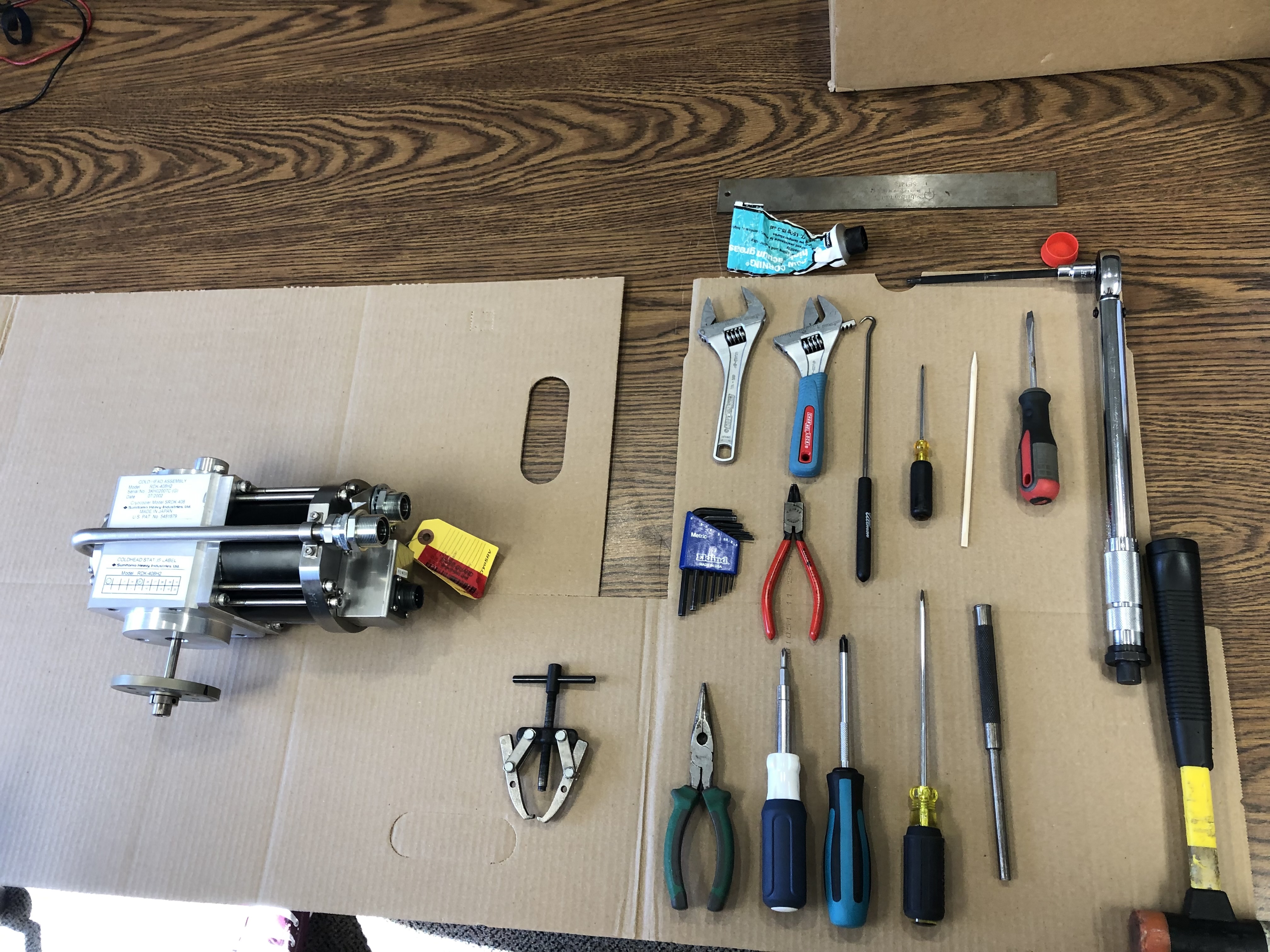
The following tools in the image below are required.
Supply Pipe
Aeroquip Bracket
Remove the M30 nuts holding on the aeroquip brackets. Be sure to back up the supply pipe to avoid twisting.
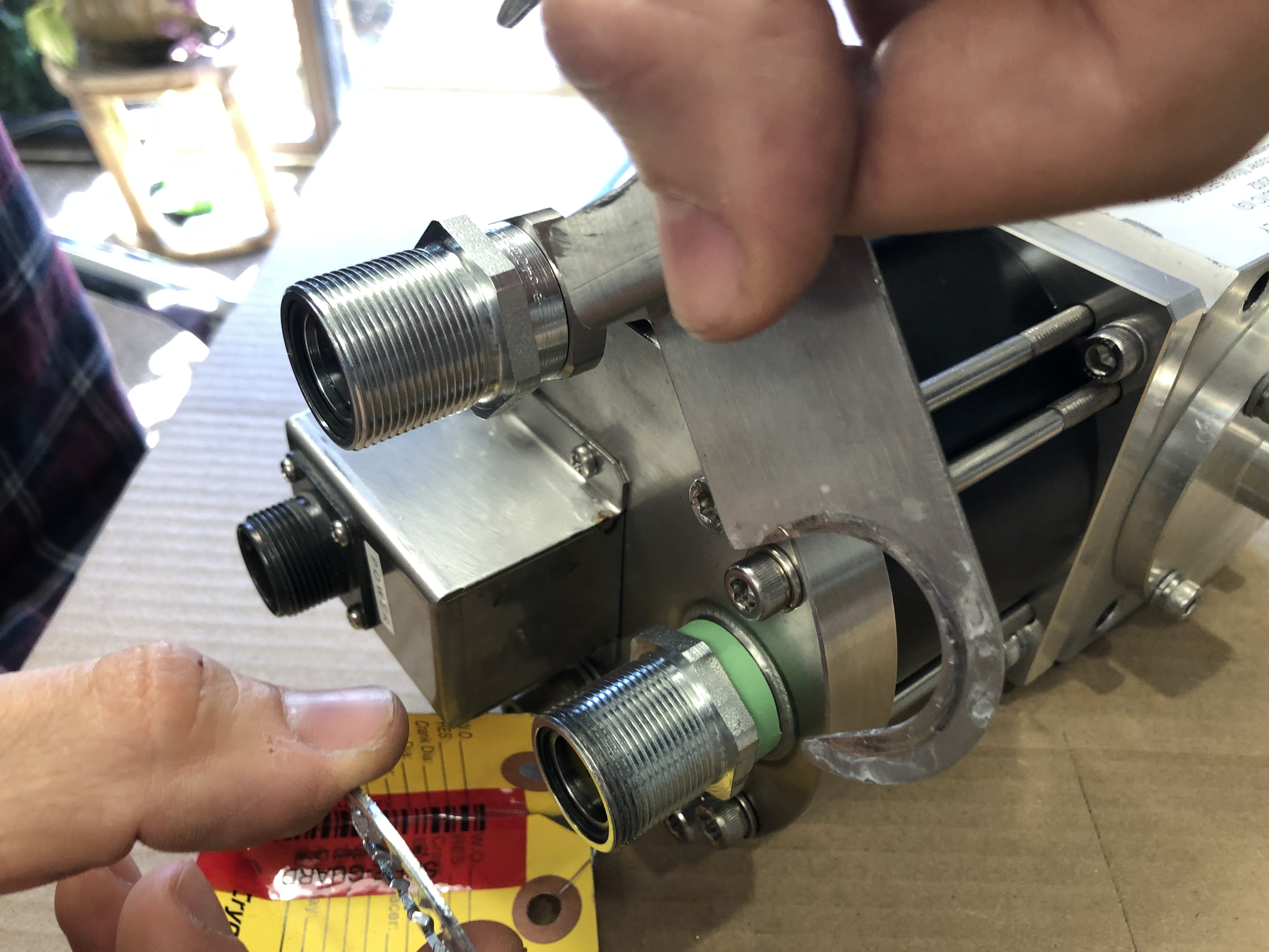
Keep the bracket. It will need to be delivered to logistics for cleaning and stocking. The bracket is a component that is added onto the cold head during the labeling and bagging phase.
Saddle
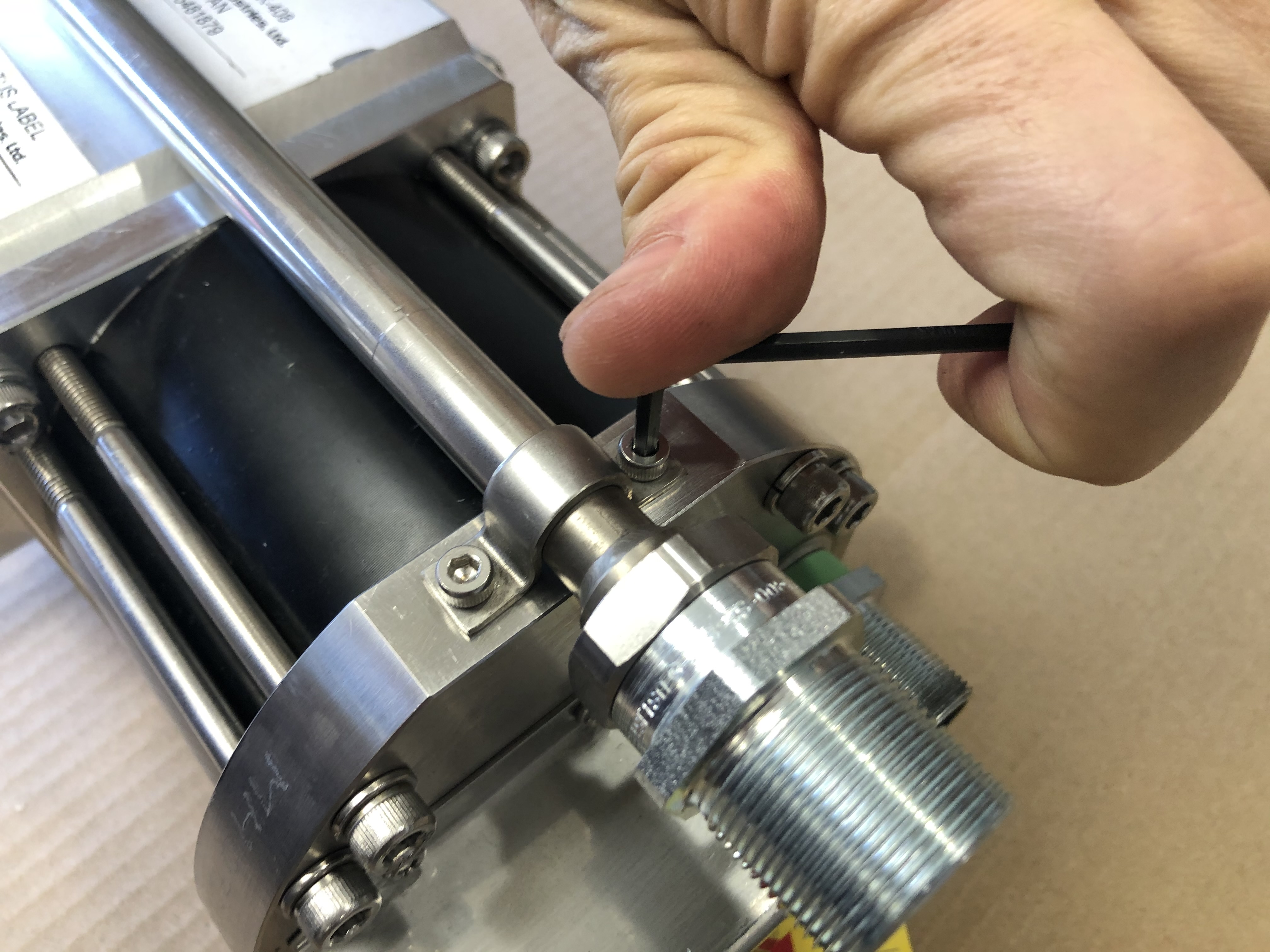
Remove the two M4 screws holding on the supply pipe saddle to the motor. This requires an M3 hex key.
Note
Do not use a ball end for loosening because they will break. Use the short end of the L key in order to gain the best mechanical advantage.
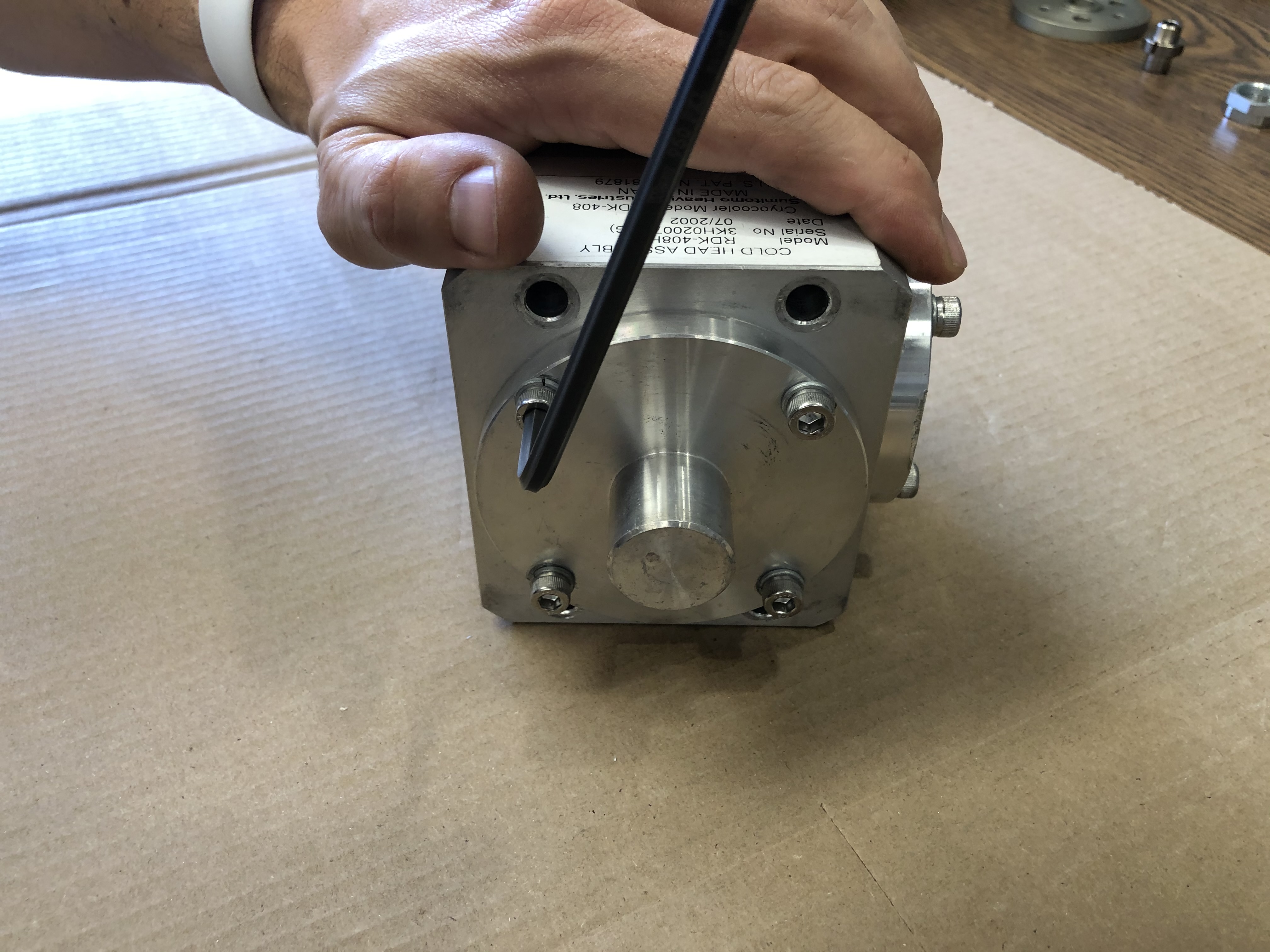
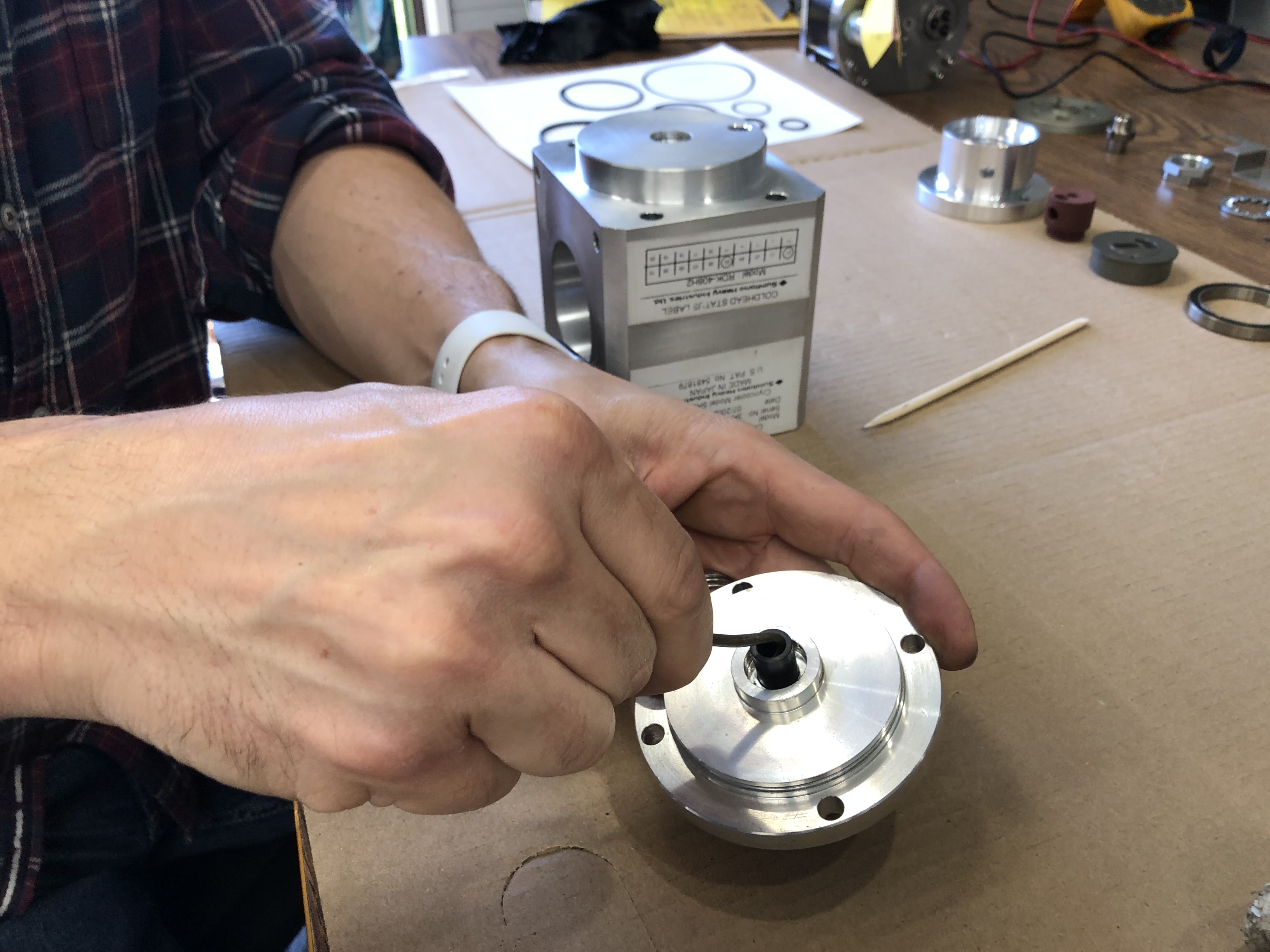
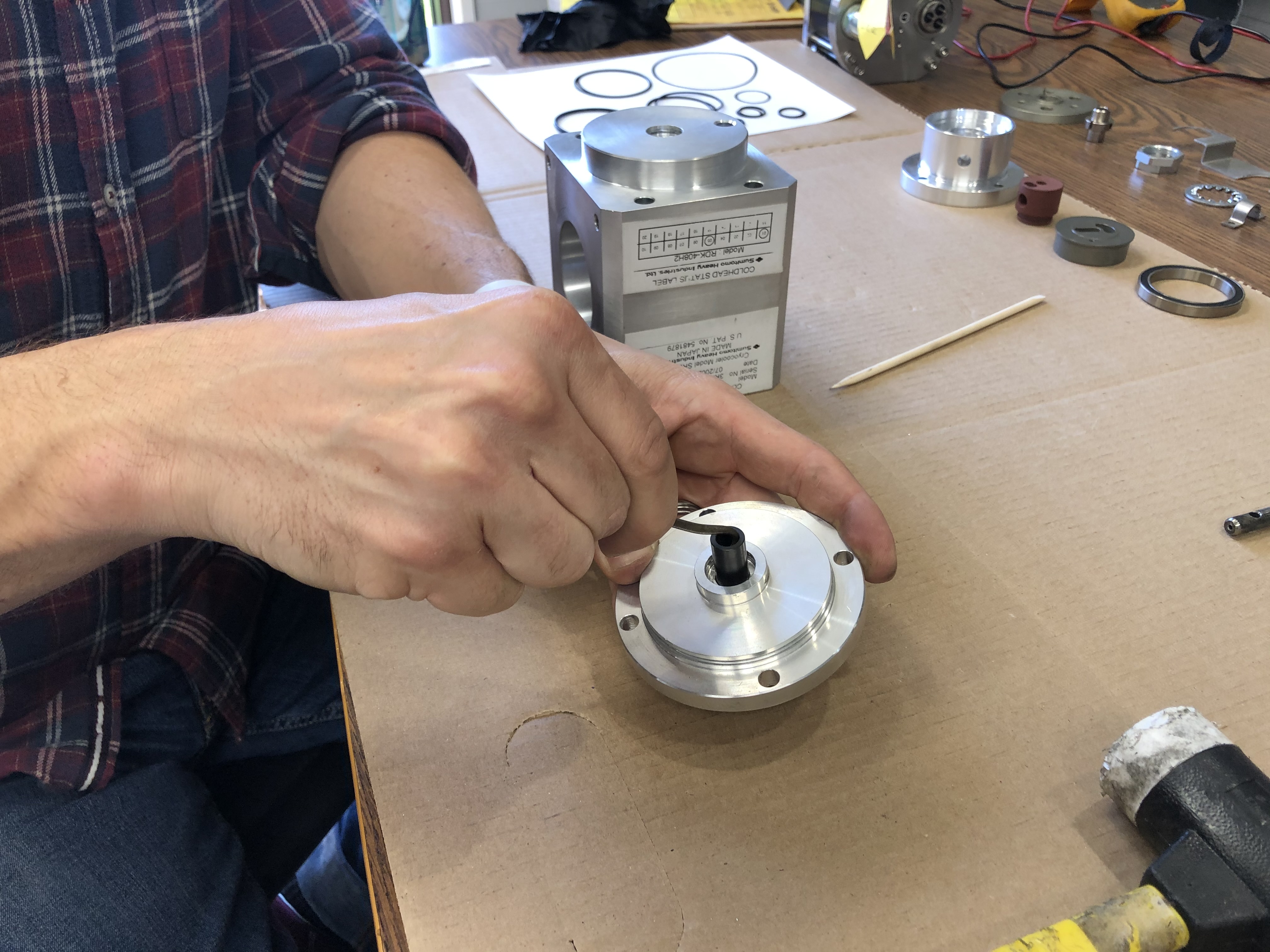
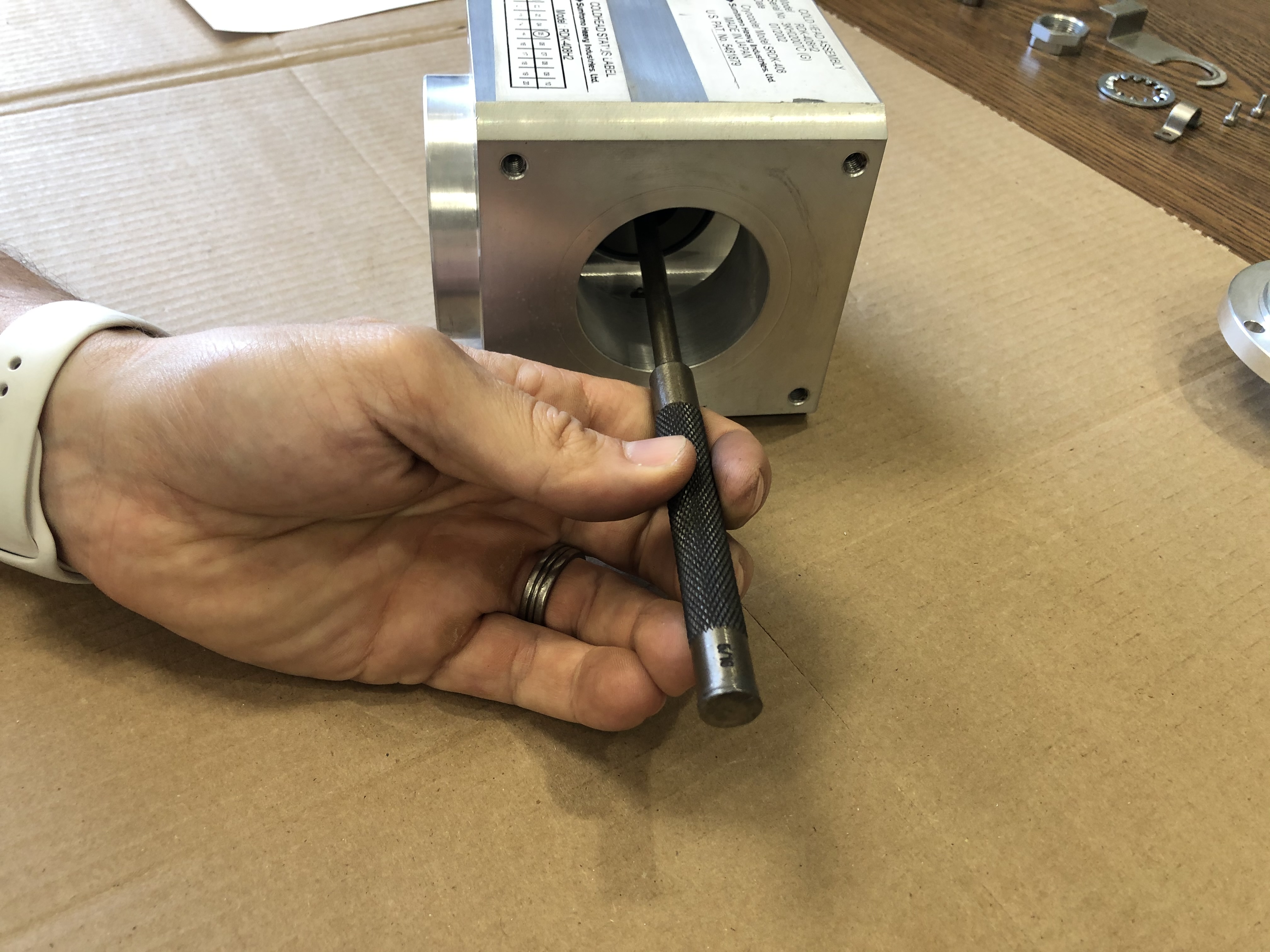
Valve Spring
Loosen the three M4 fasteners on the back of the supply pipe to the valve body. This also uses an M3 hex key.
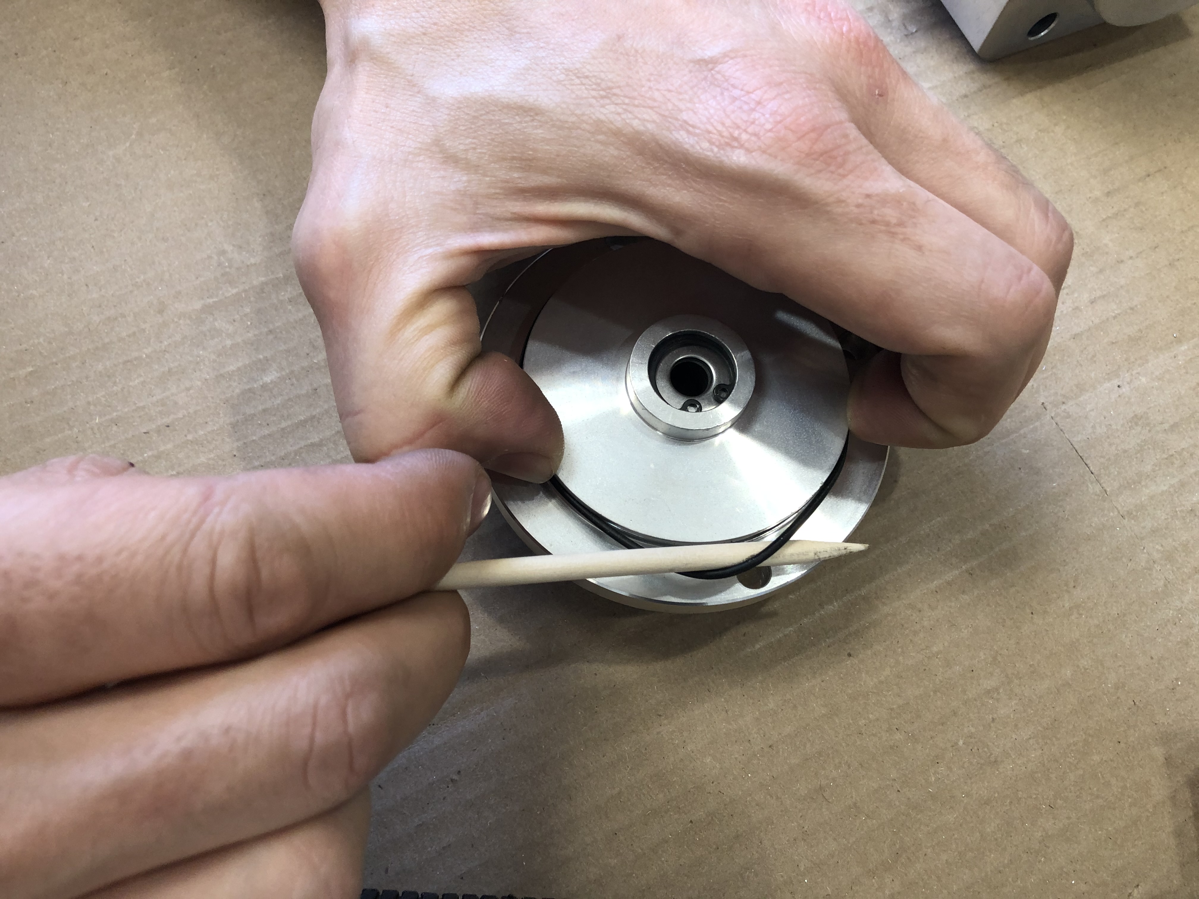
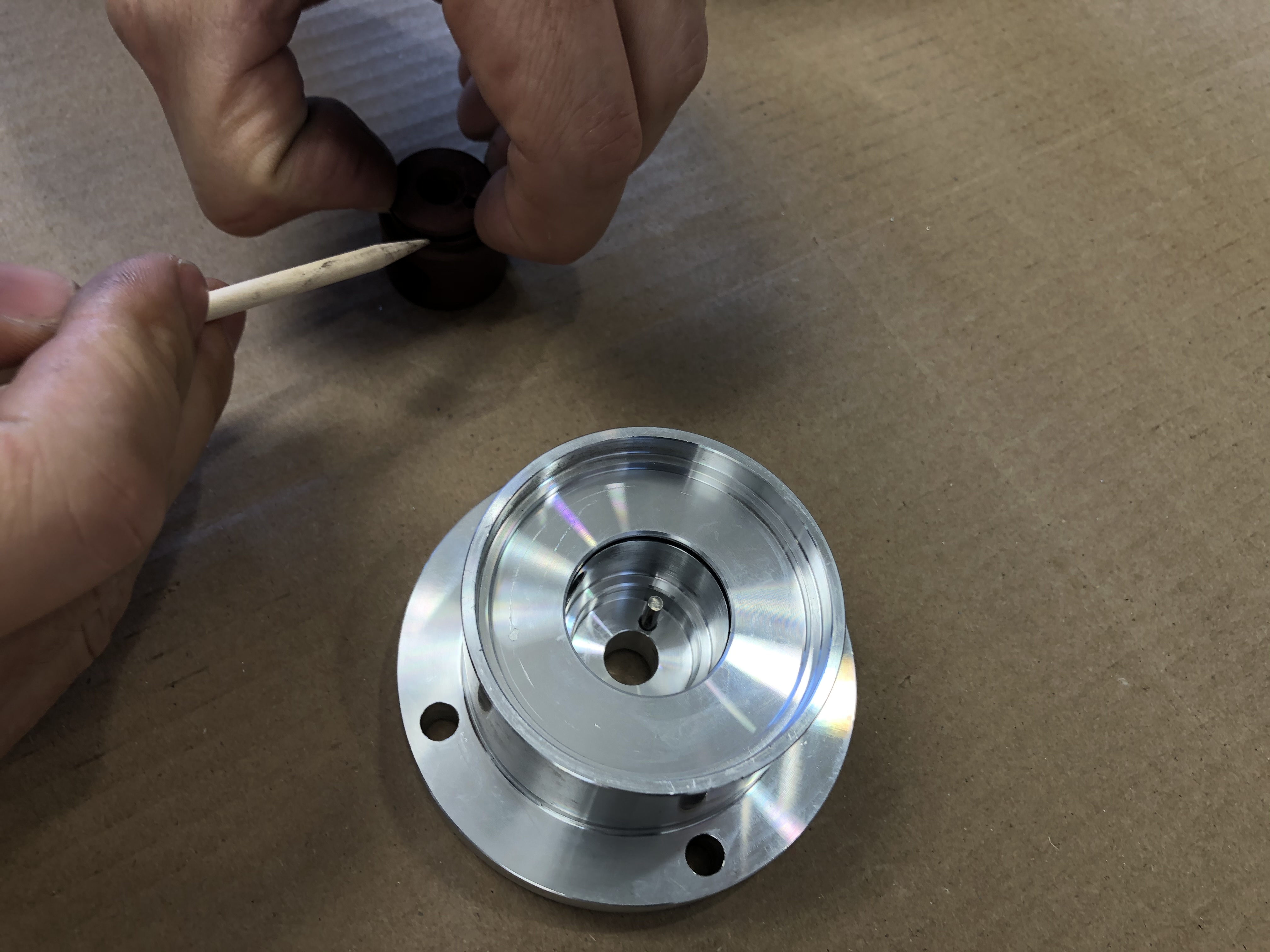
Remove the supply pipe revealing the valve spring resting inside the valve body. Remove the valve spring.
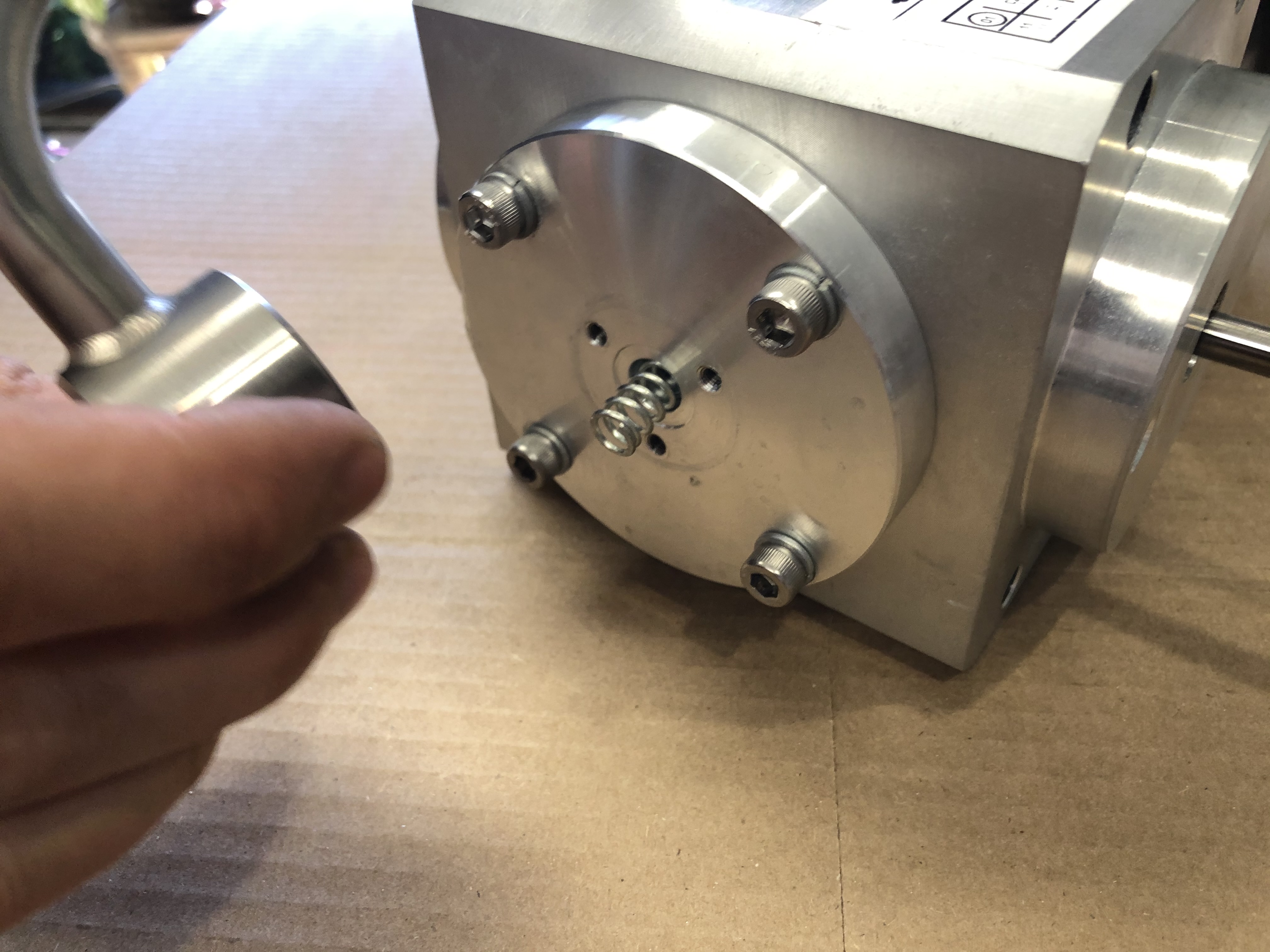
Remove and disgard the supply pipe oring.
Warning
Using metal pics and instruments will scratch the soft metal sealing surfaces. Much of this cold head is made from machined aluminum which will scrath easily creating leaks.
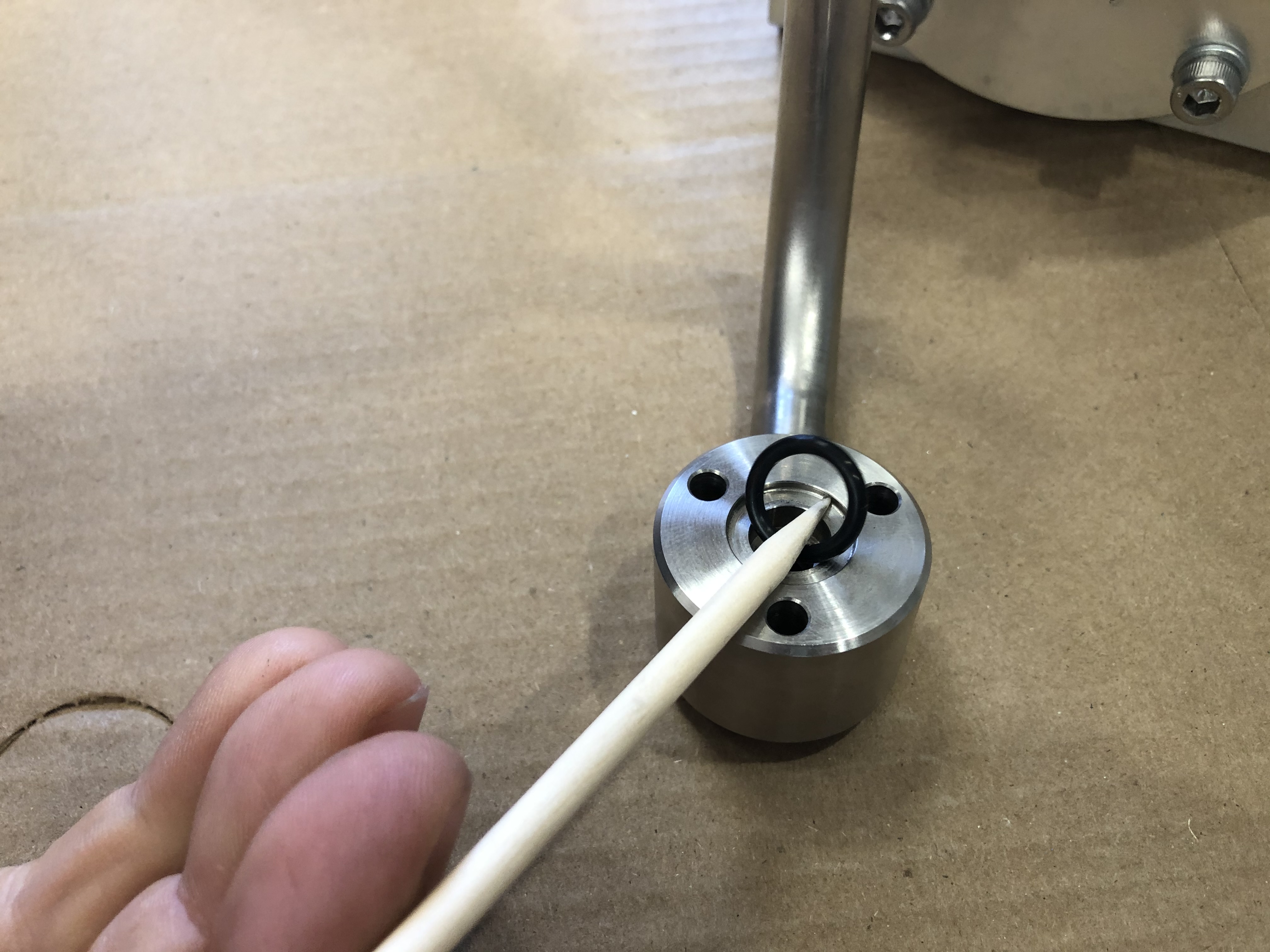
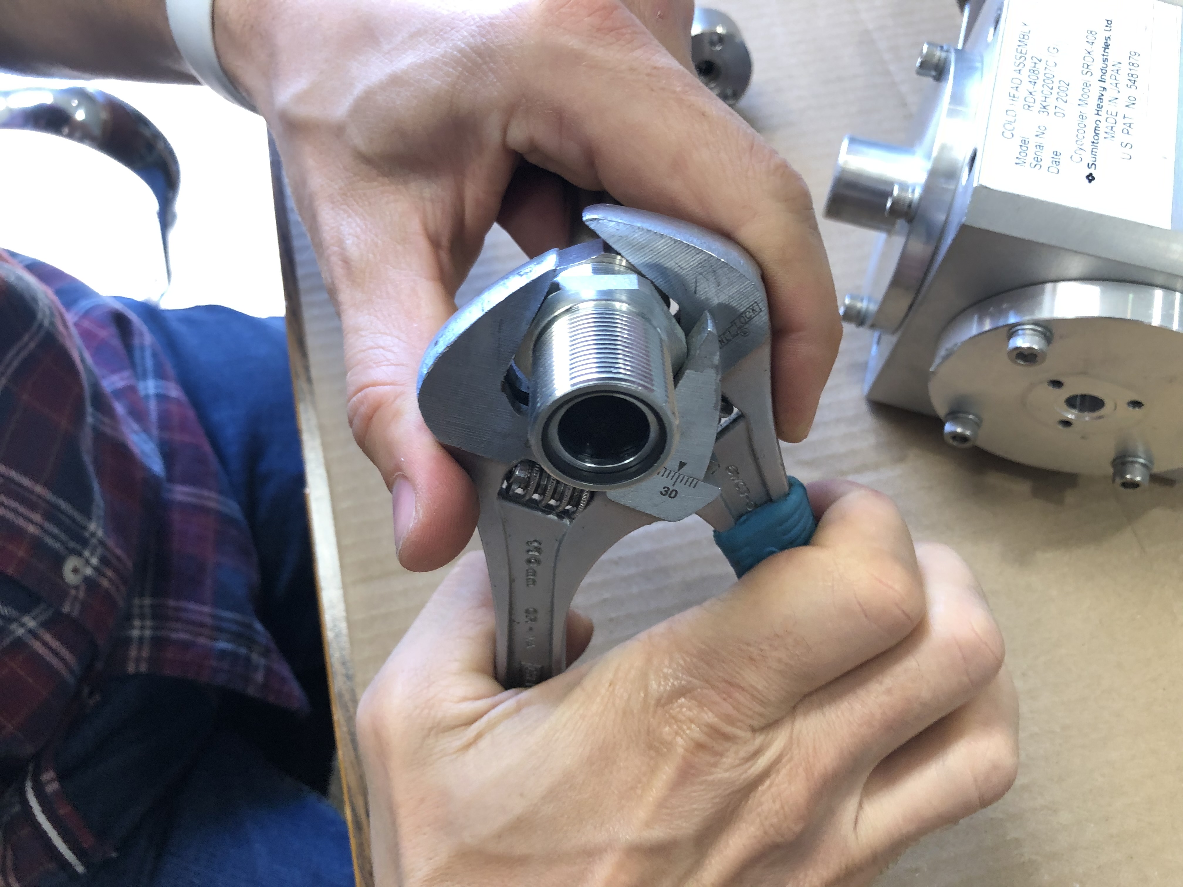
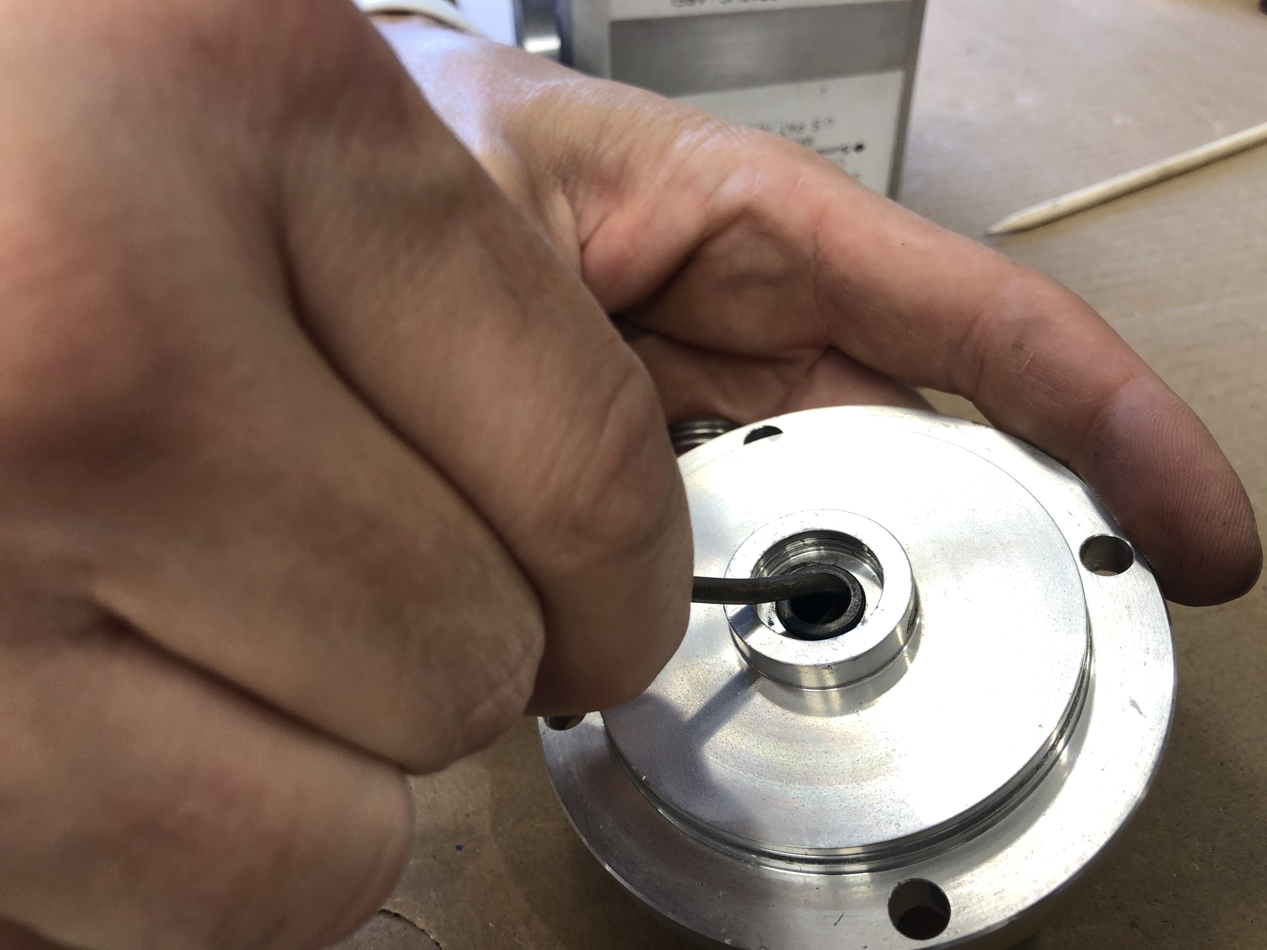
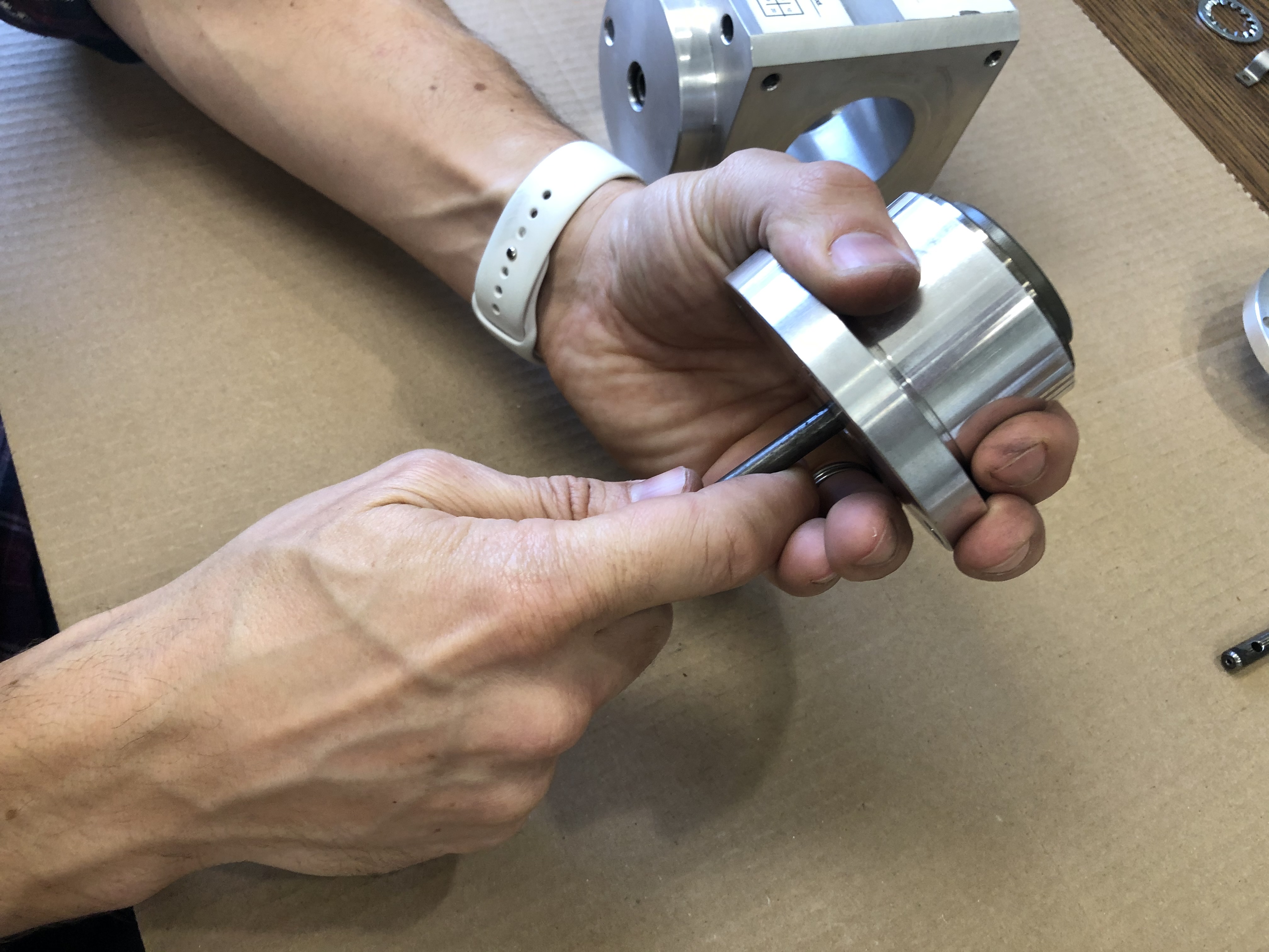
Supply Pipe Aeroquip
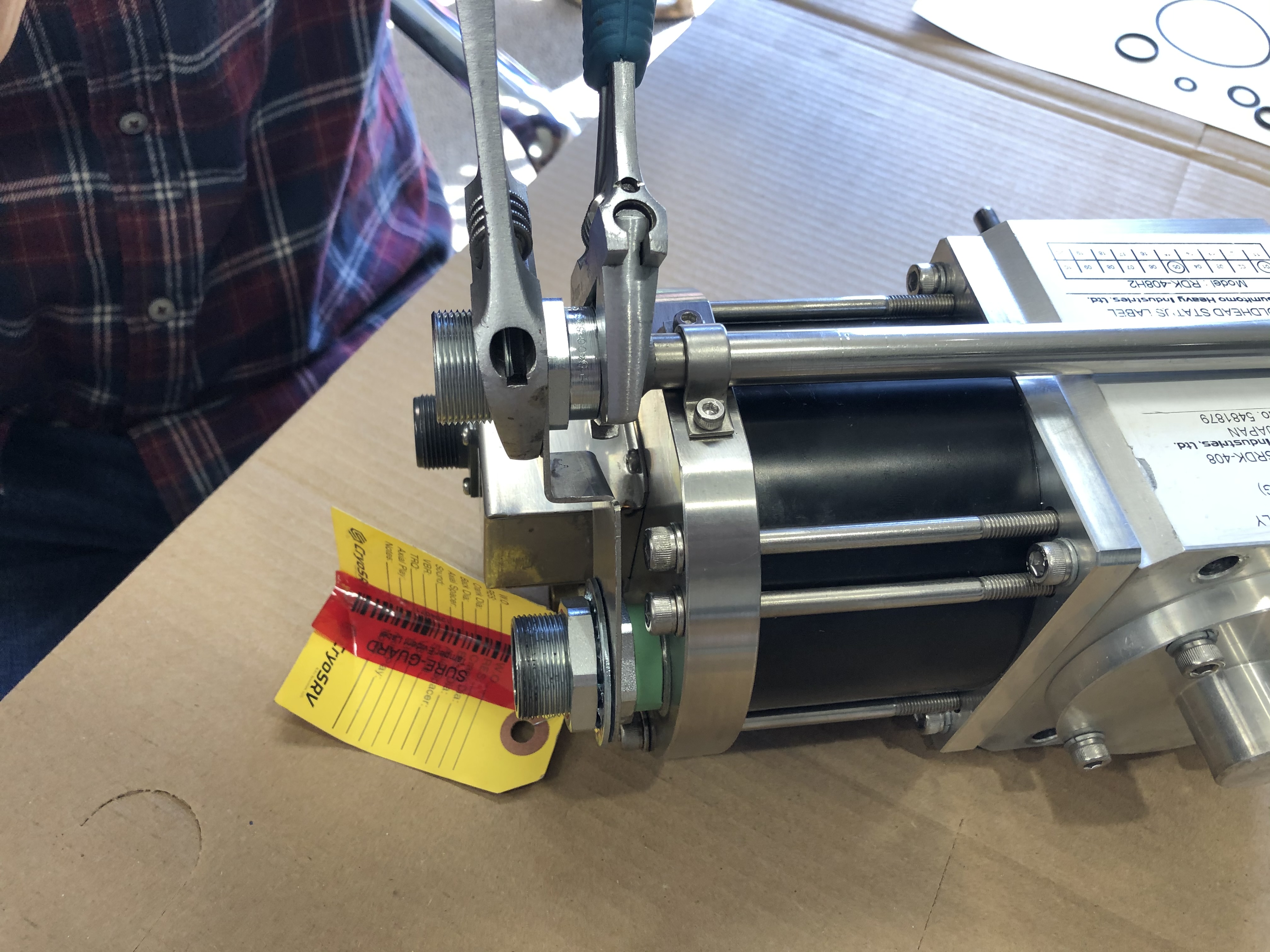
Remove the aeroquip at the end of the supply pipe by using two wrenches to losen the fitting. Depicted here are two adjustable wrenches, which will work. Technicians will have access to the proper sized wrenches for this task.
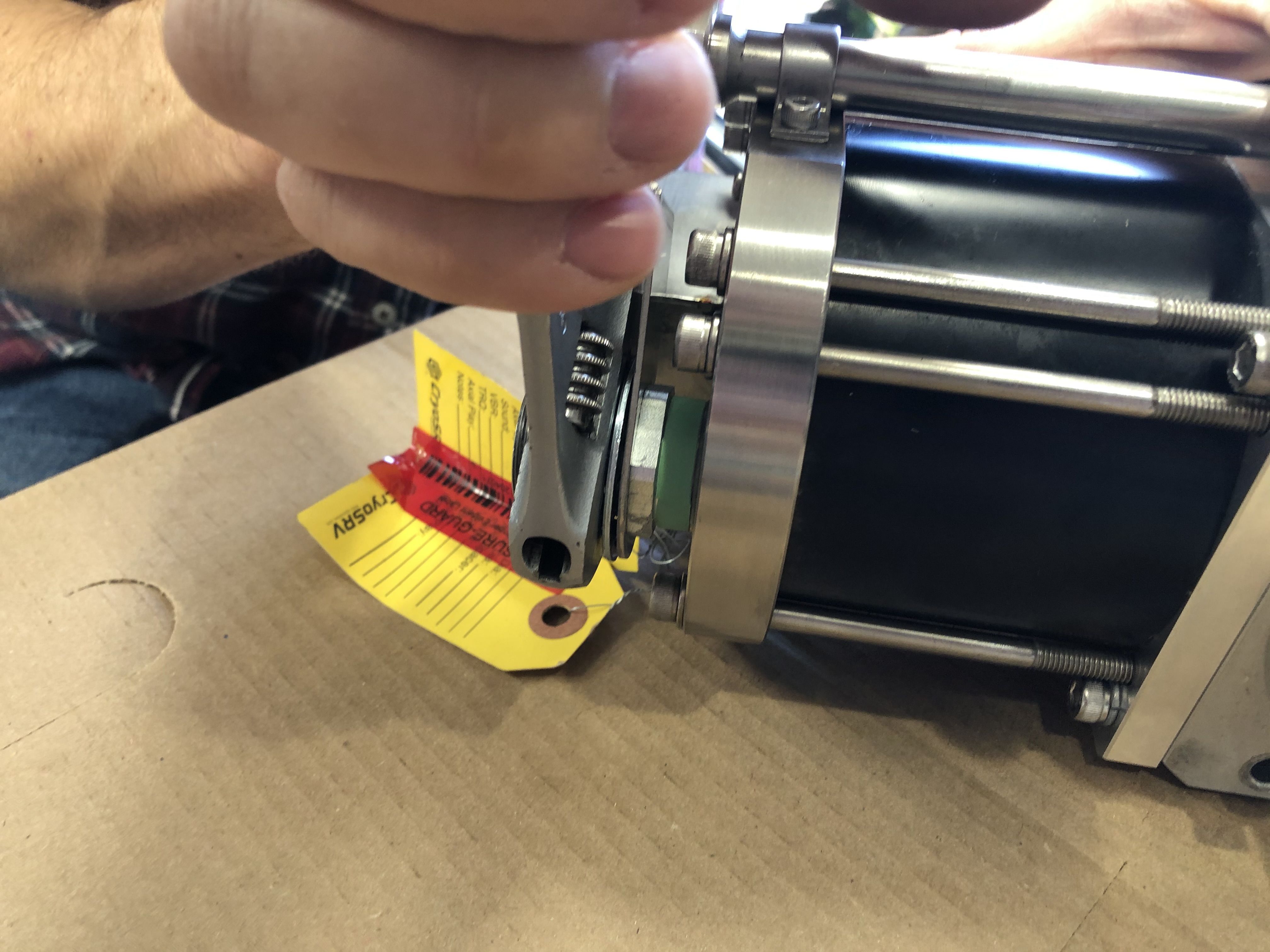
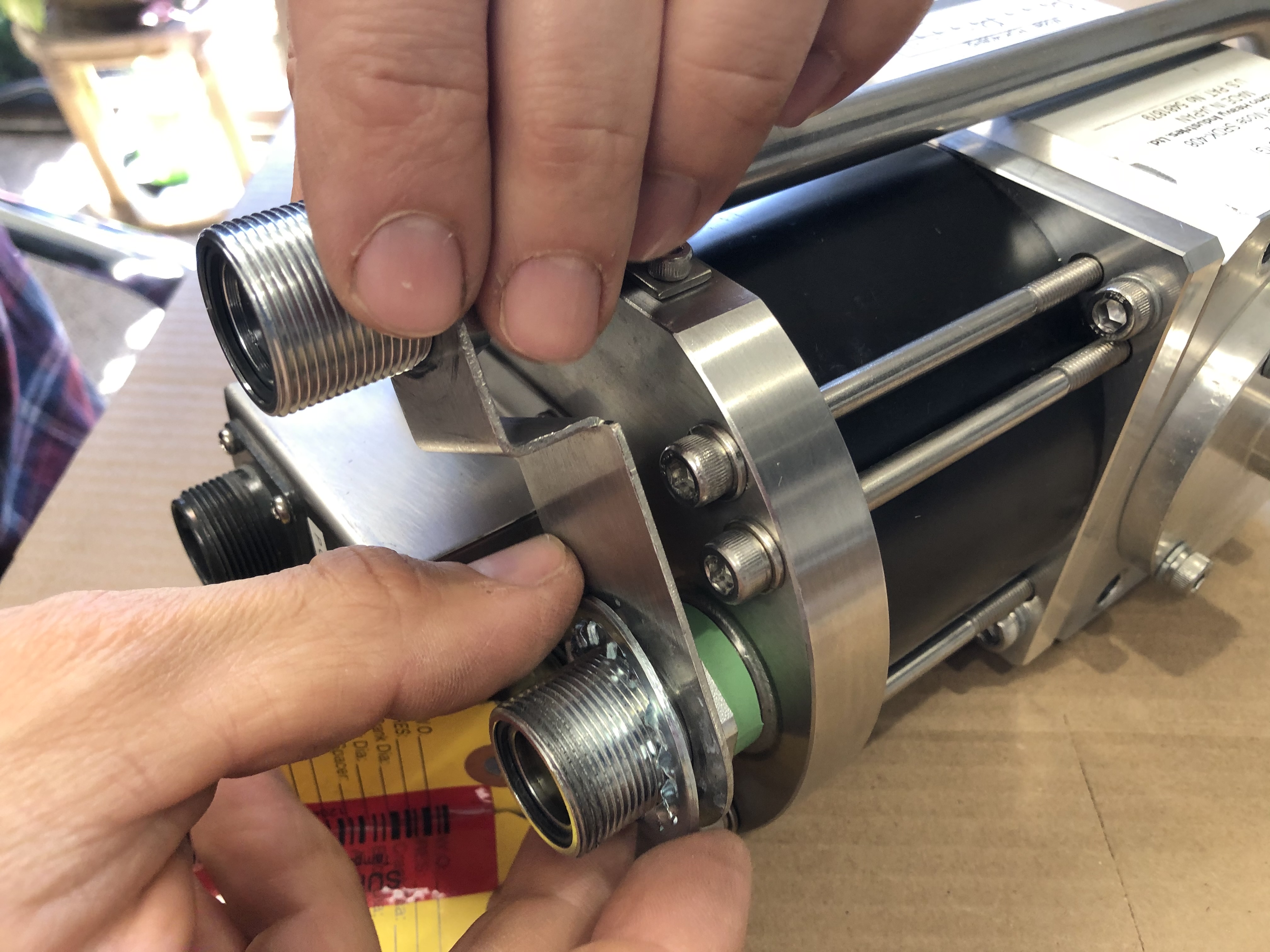
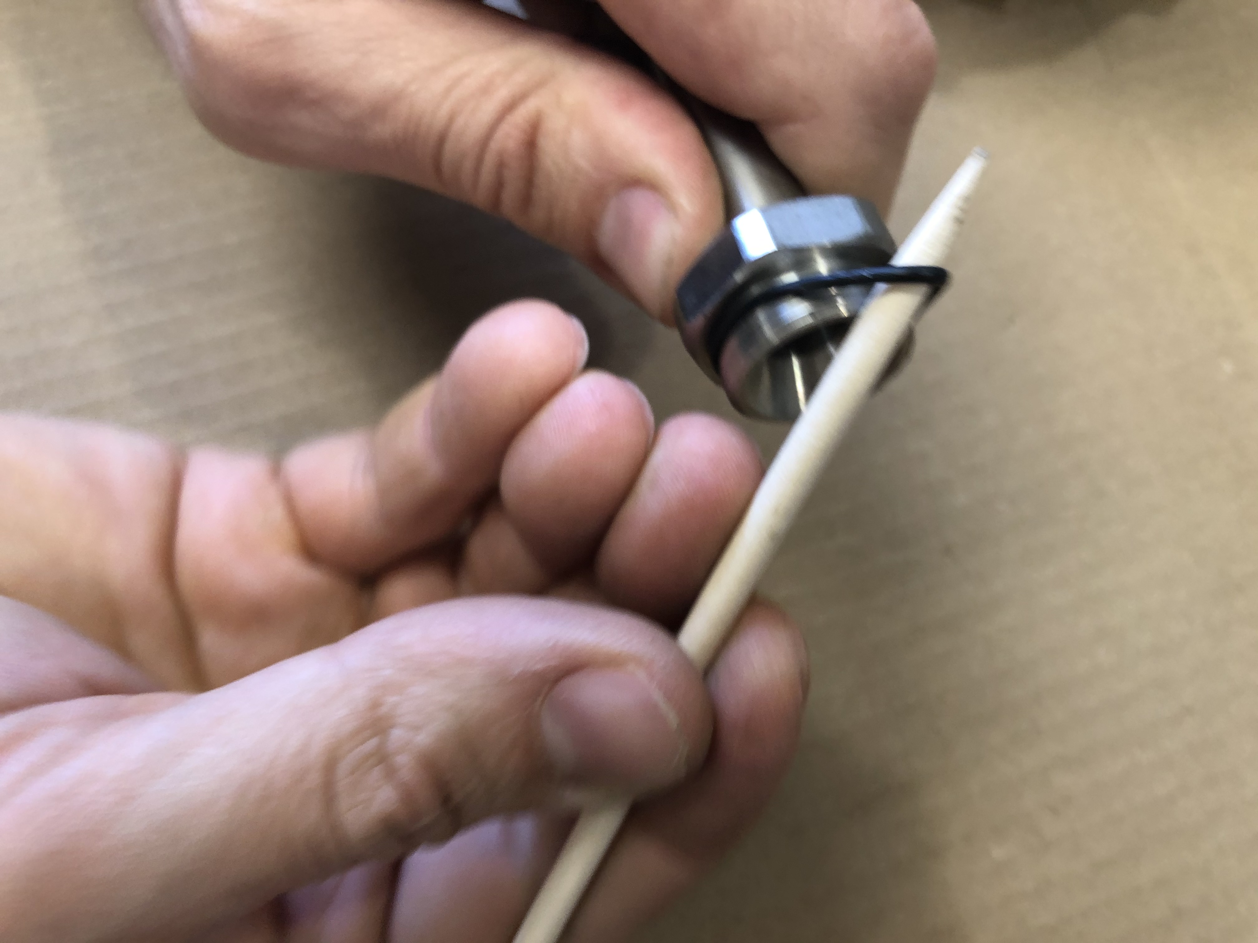
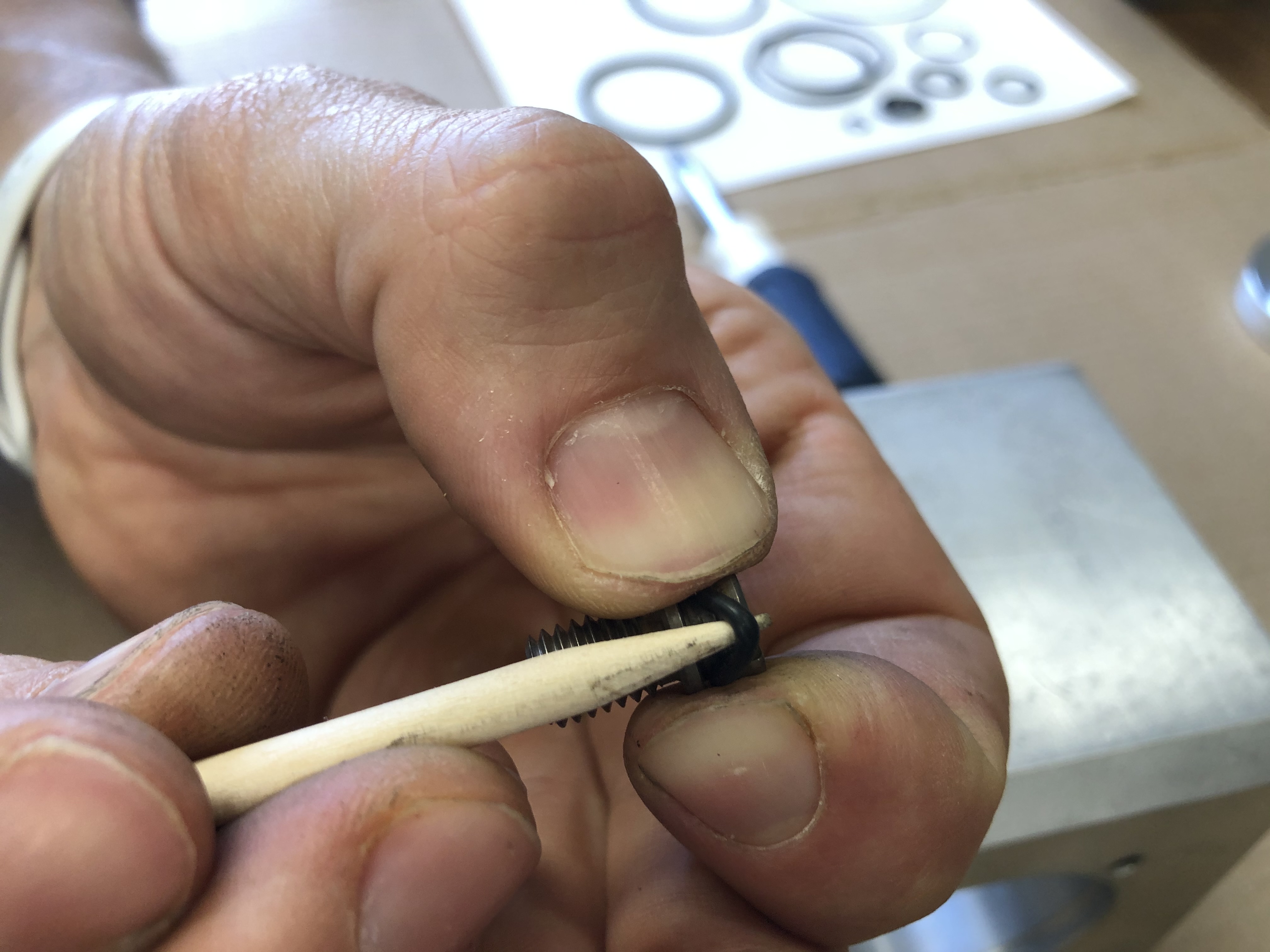
Remove the supply pipe aeroquip o-ring with a non-marring pick.
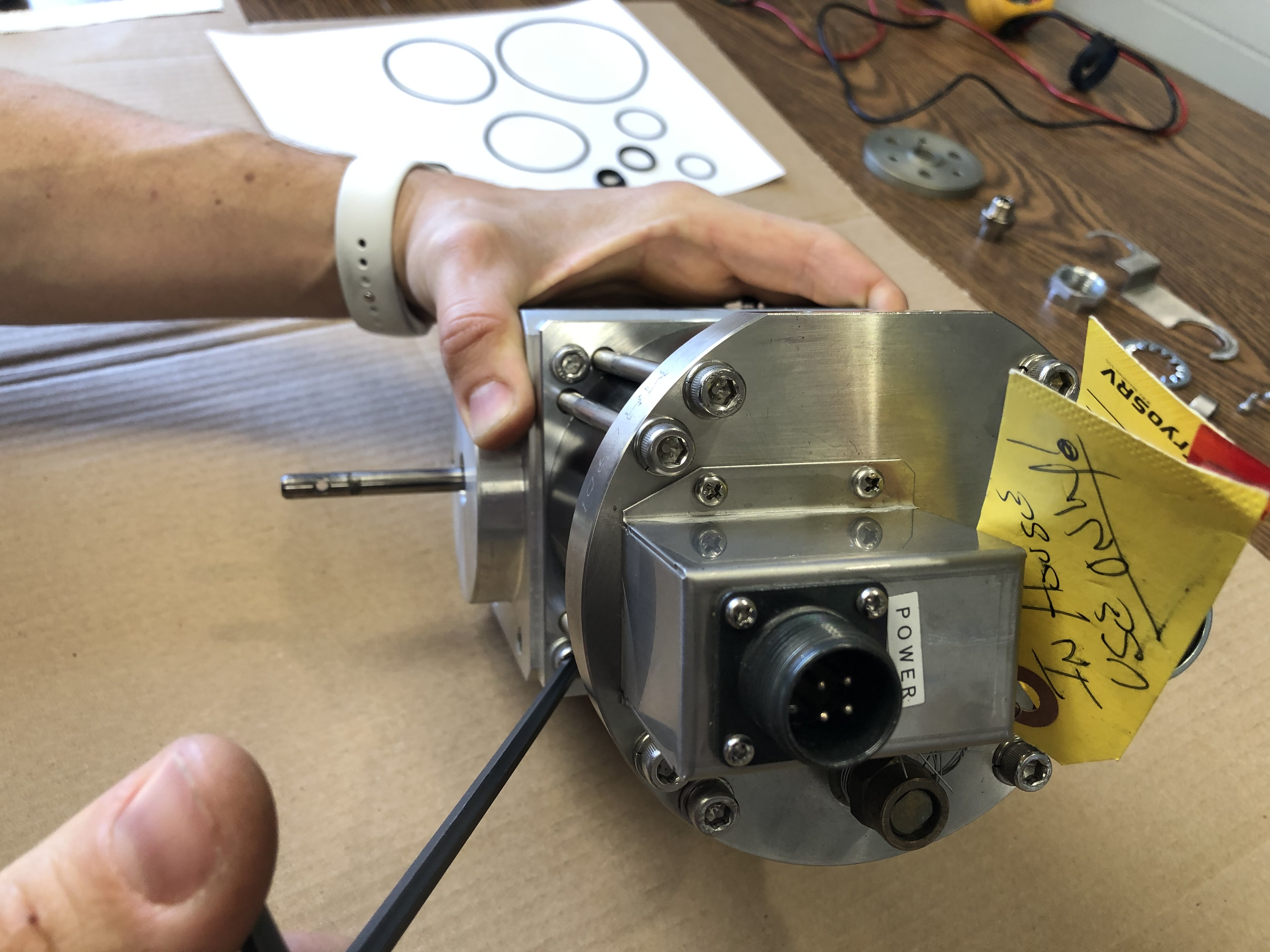
Motor
Motor to Housing
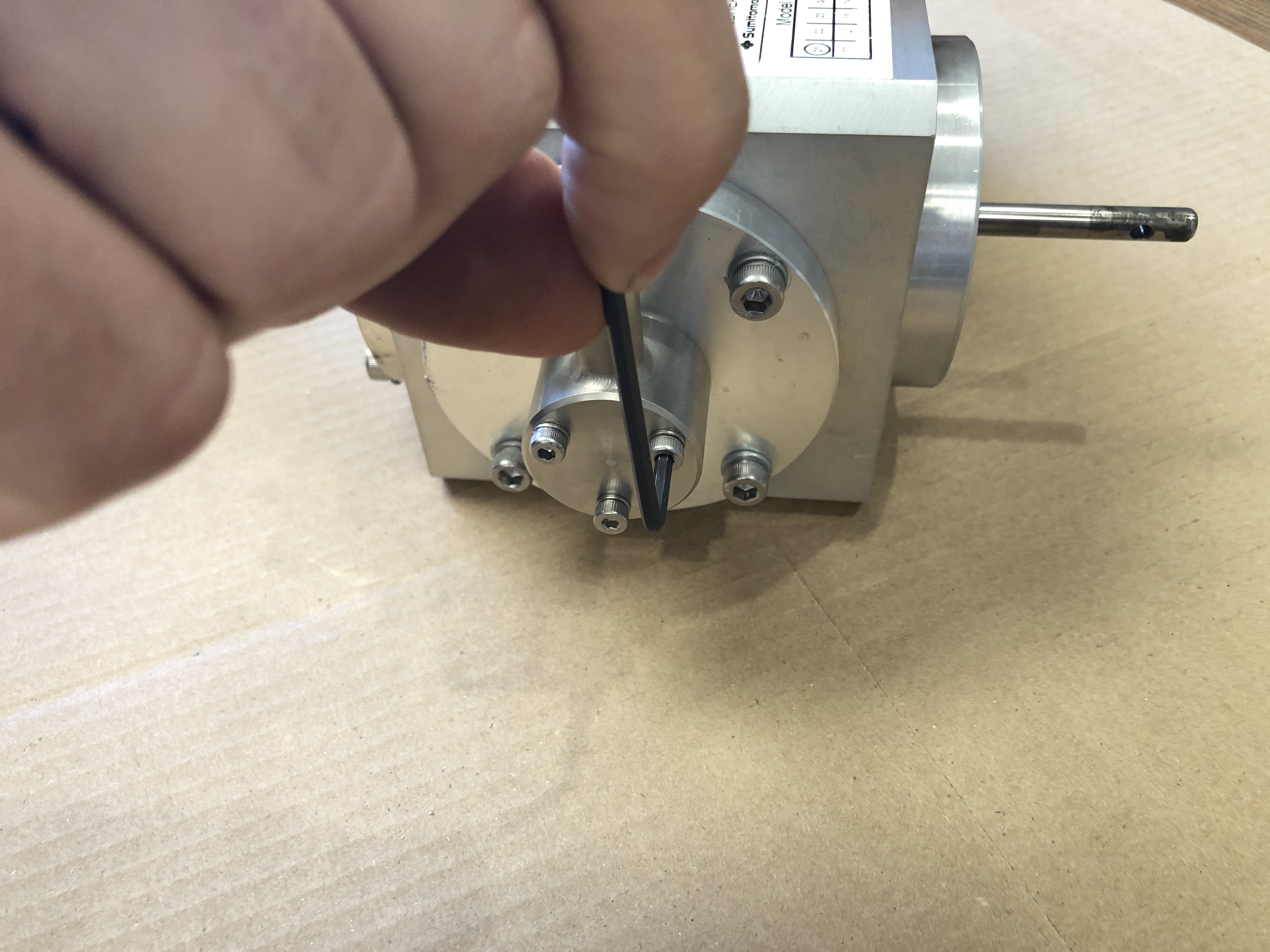
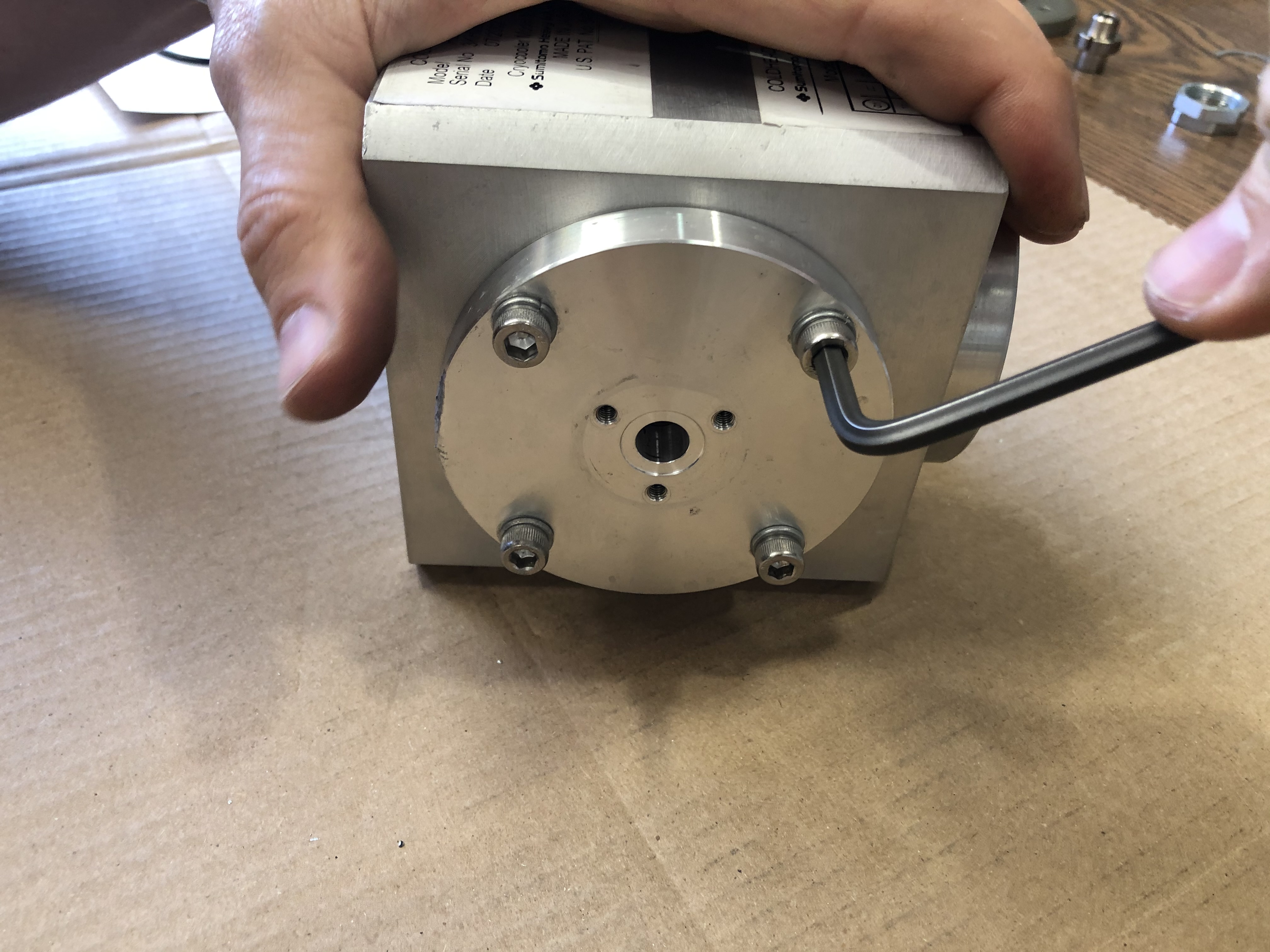
Loosed the four M6 fasteners mounting the motor assembly to the cold head housing assembly. This is a 5mm hex key.
Tip
Losen all the fasteners on the underside of the motor then remove the top side fasteners to maintain the orientation of the cold head housing assembly.
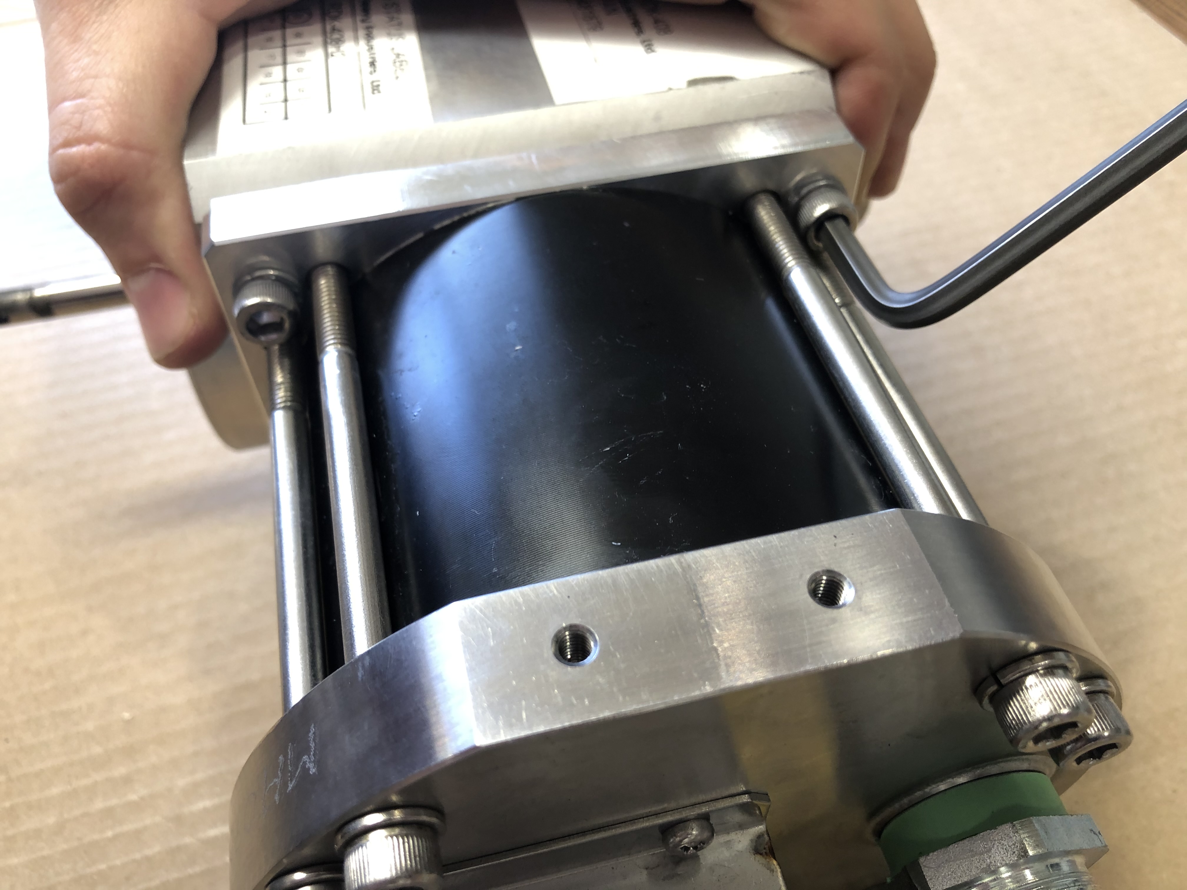
Once all the M6 mounting fasteners are removed lay the assembly flat so that both the motor assembly and the housing assebly are supported.
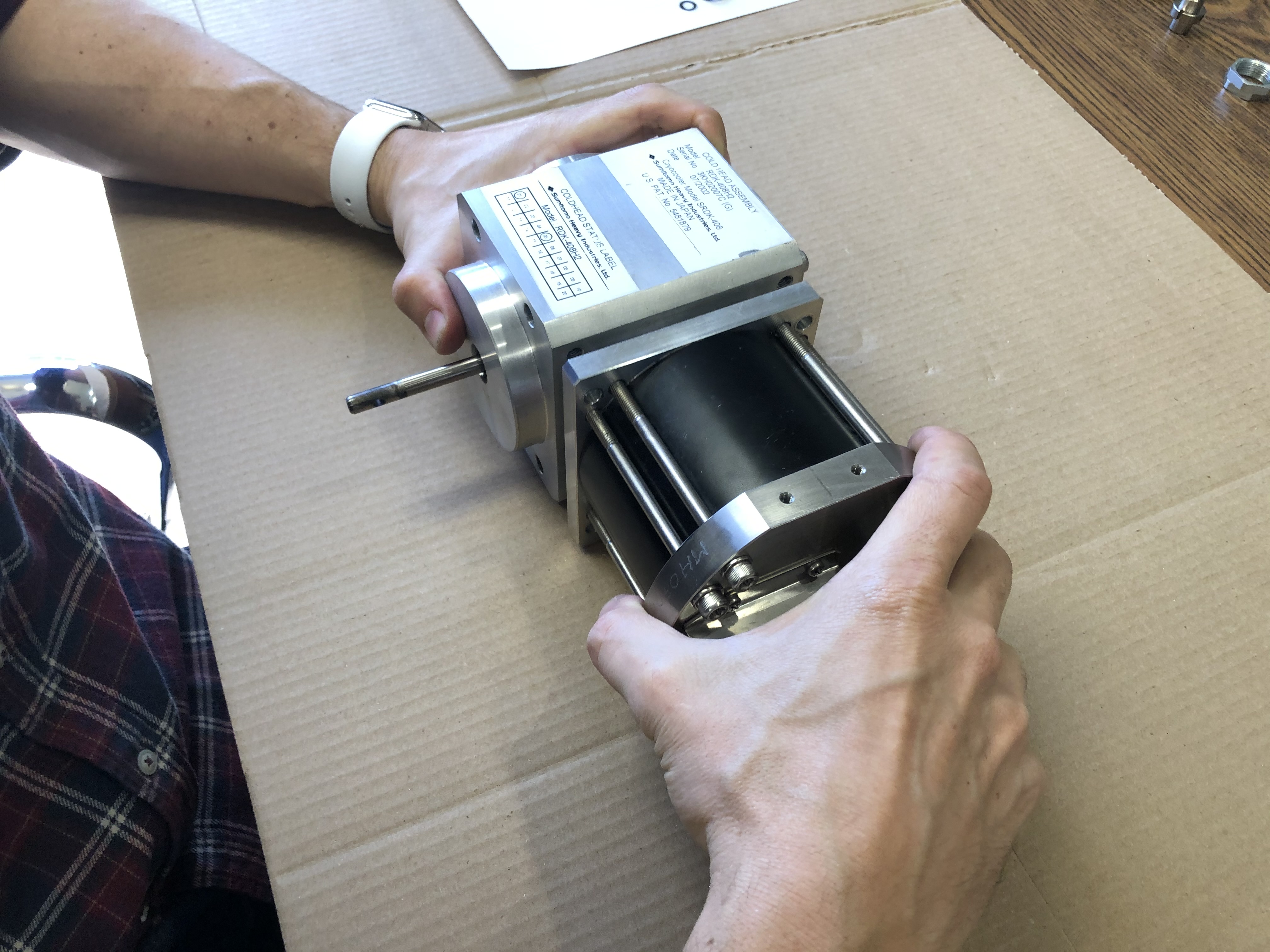
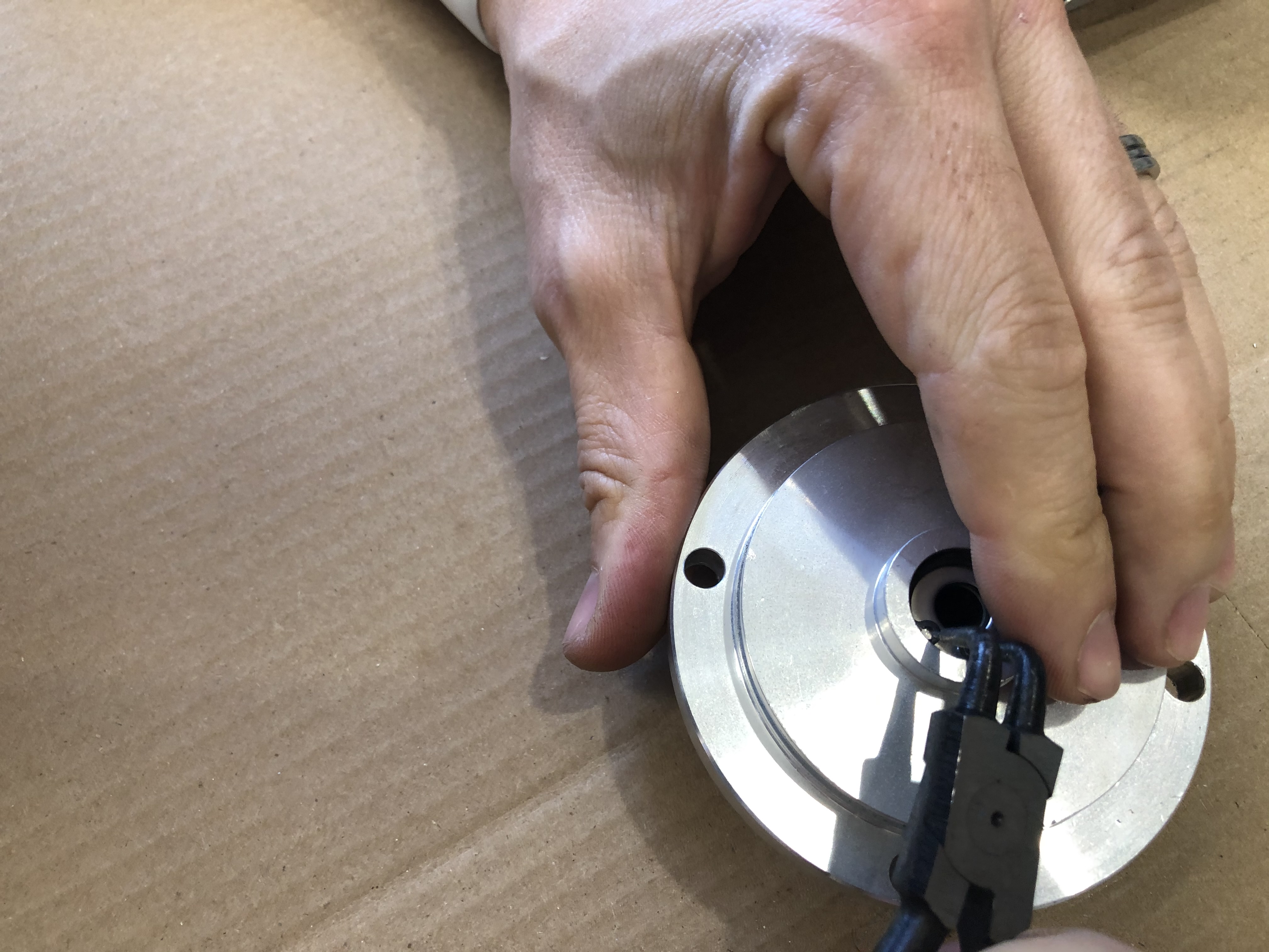
Slide the motor assembly free of the housing assembly.
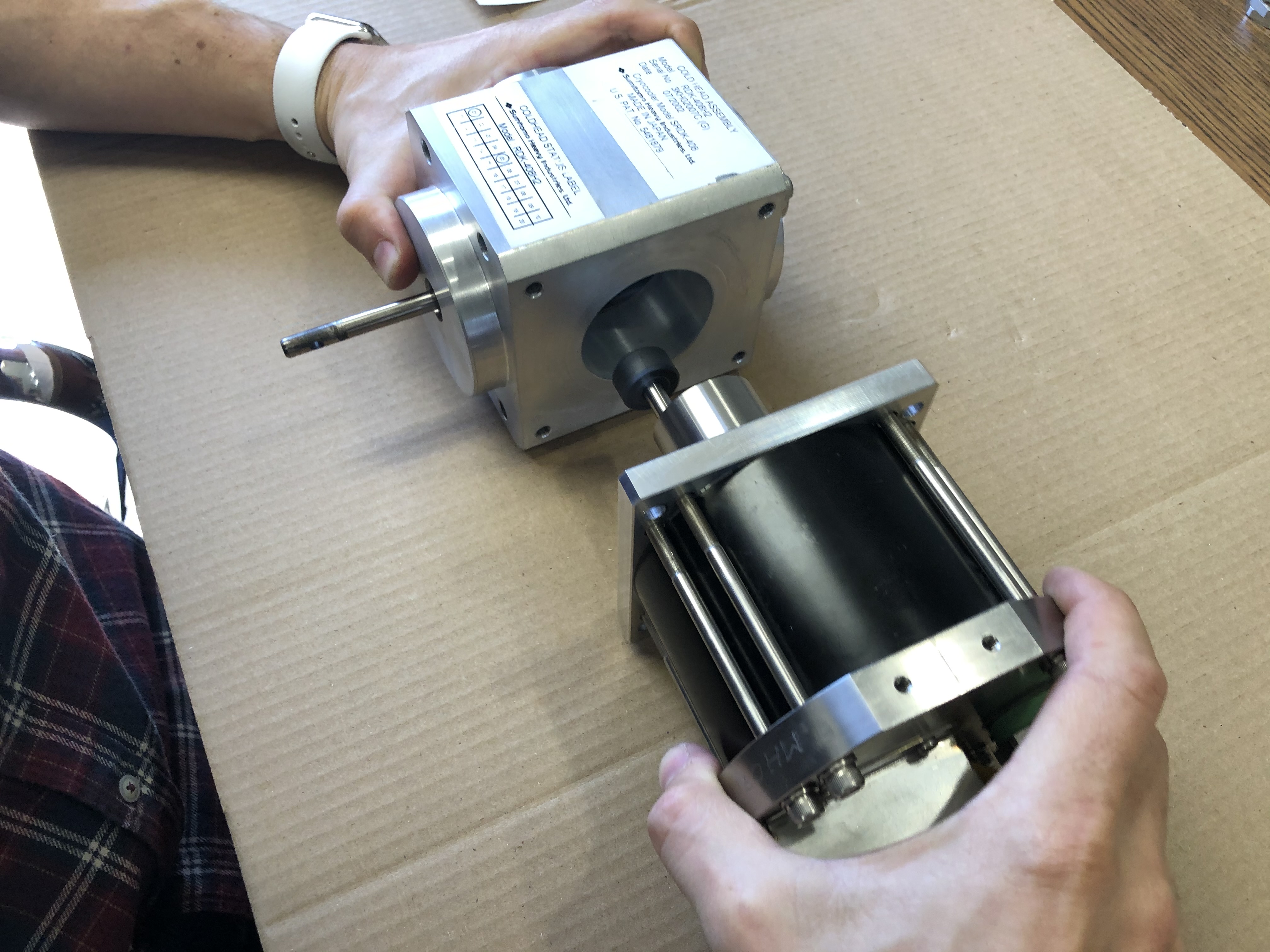
Inspect the motor crank bushing for any gauling or uneven wear. With mild to severe oil contamination you should be ablt to identify liquid oil on the motor crank, the motor front plate, and the crank case. If any oil is discovered take images of the areas in detail and upload them to the Trello card. Flag the card as OIL FOUND and press the ATT: SALES button.
Success
From this point you will follow the individual cold head models refubishment instructions for handling the motor assembly.
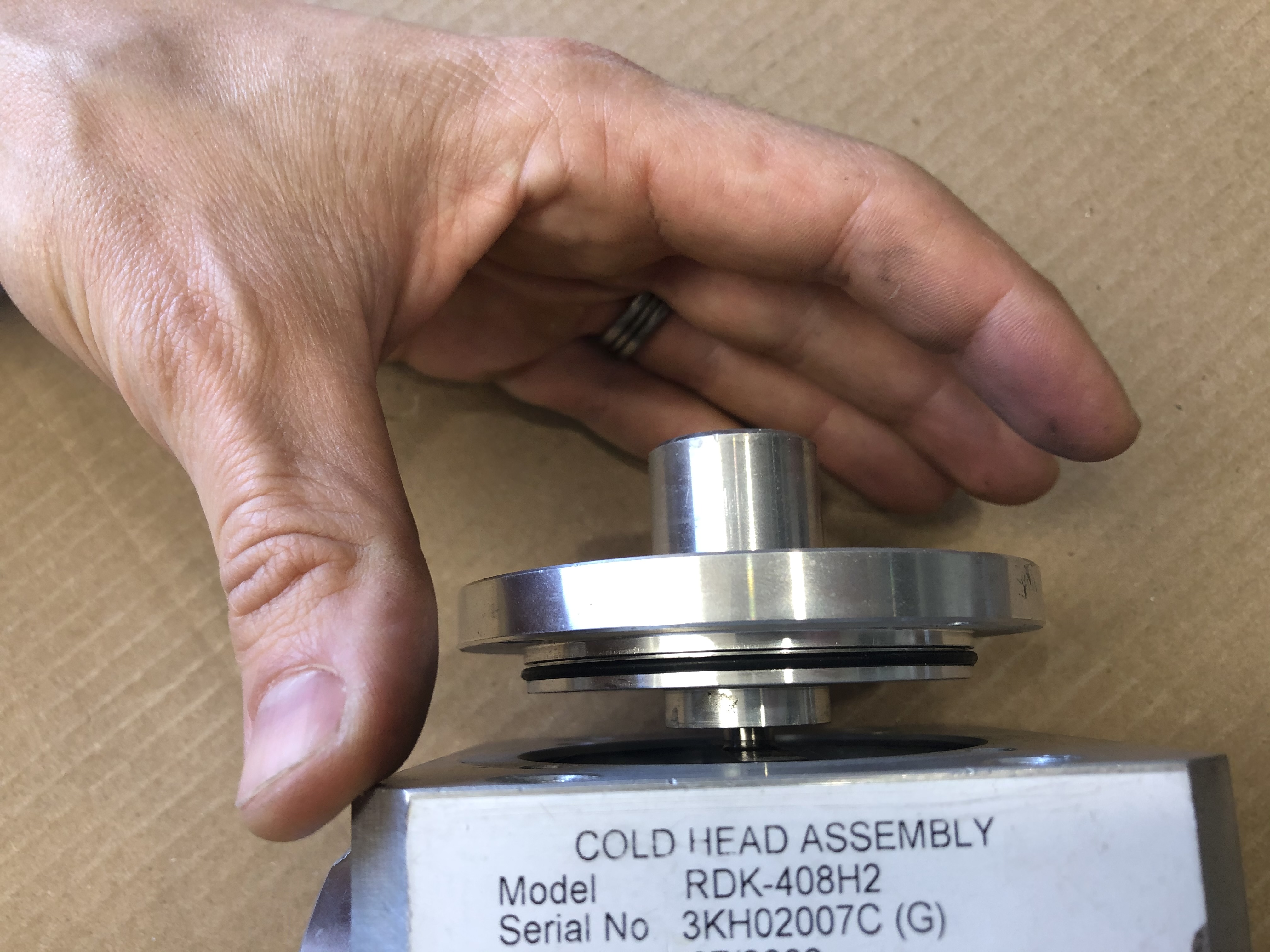
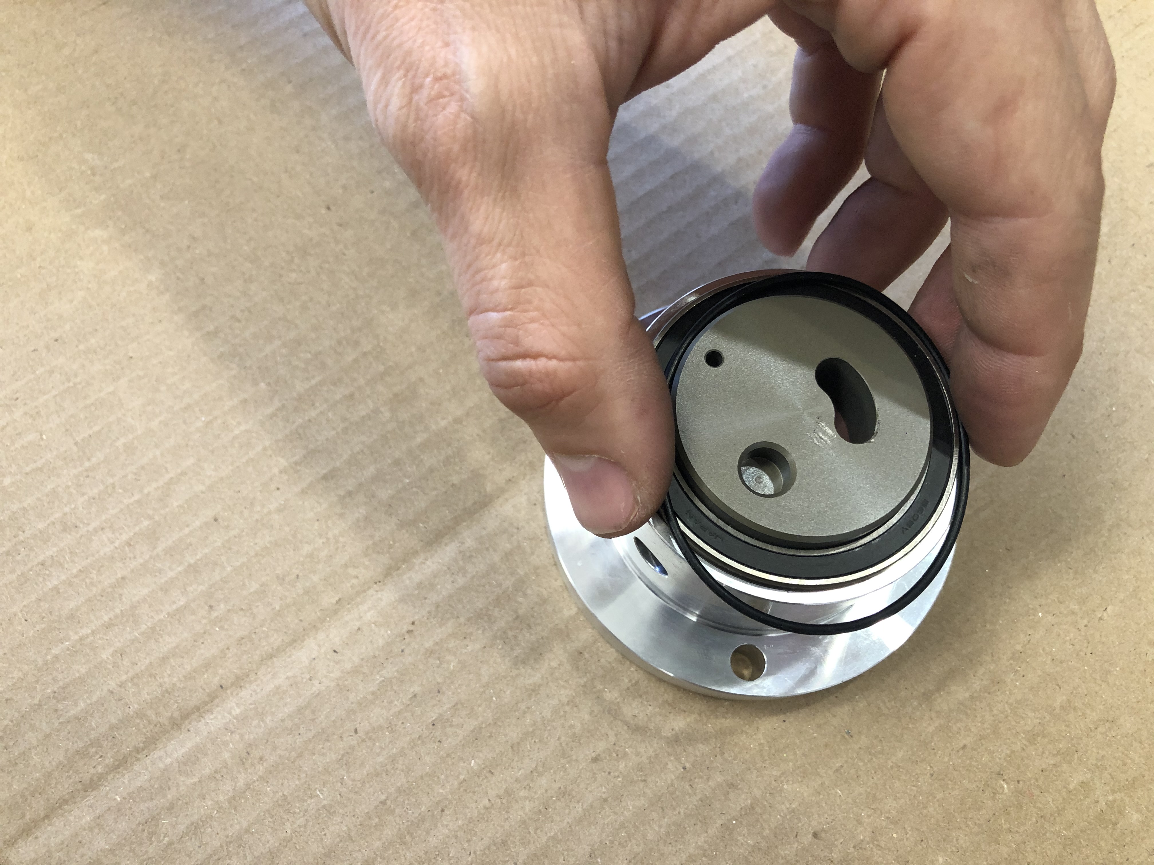
Upper Cup
The upper cup contains the channel for the back end of the scotch yoke to travel. This sub assembly contains several components that need to be removed during the diassembly.
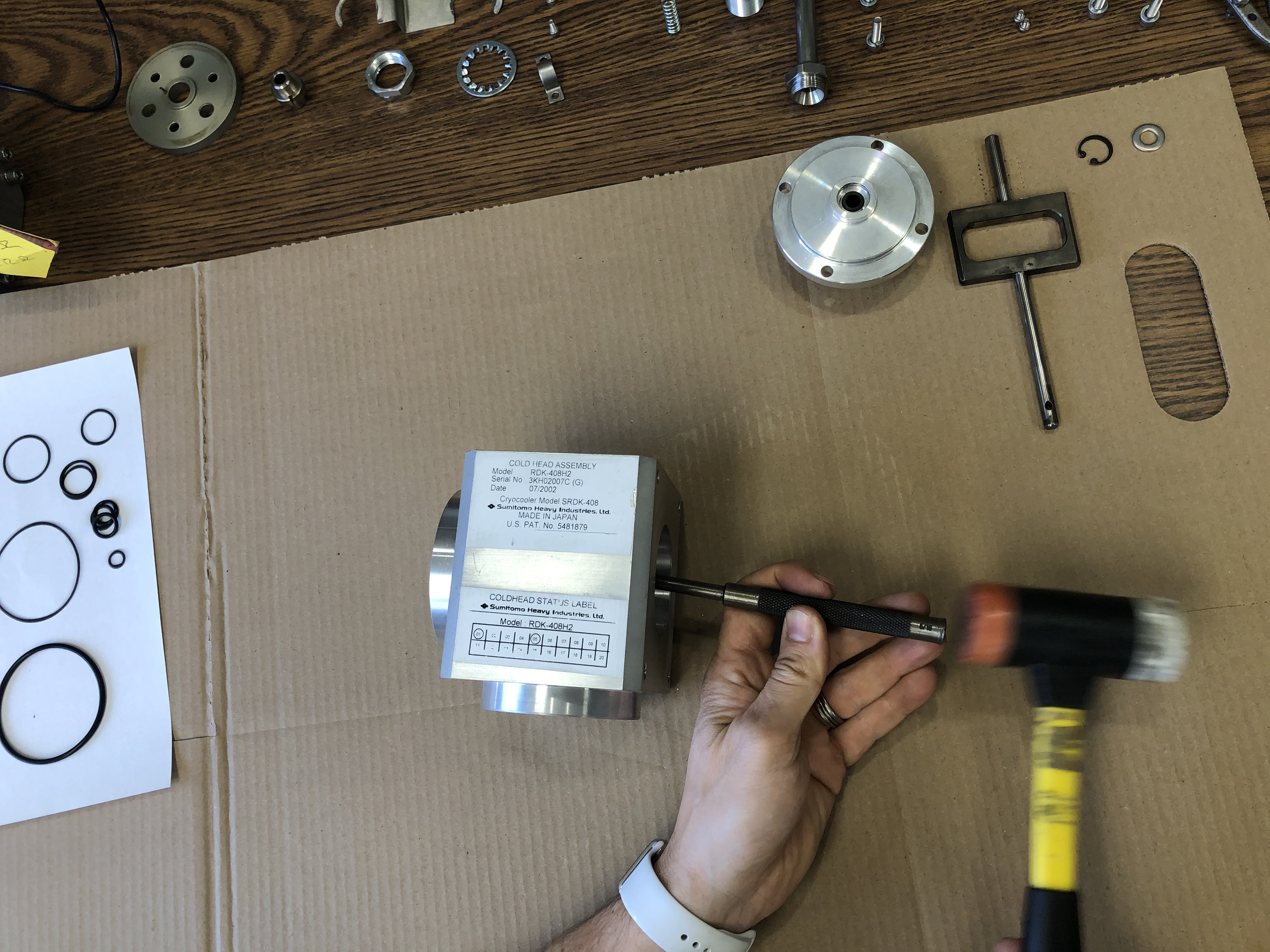
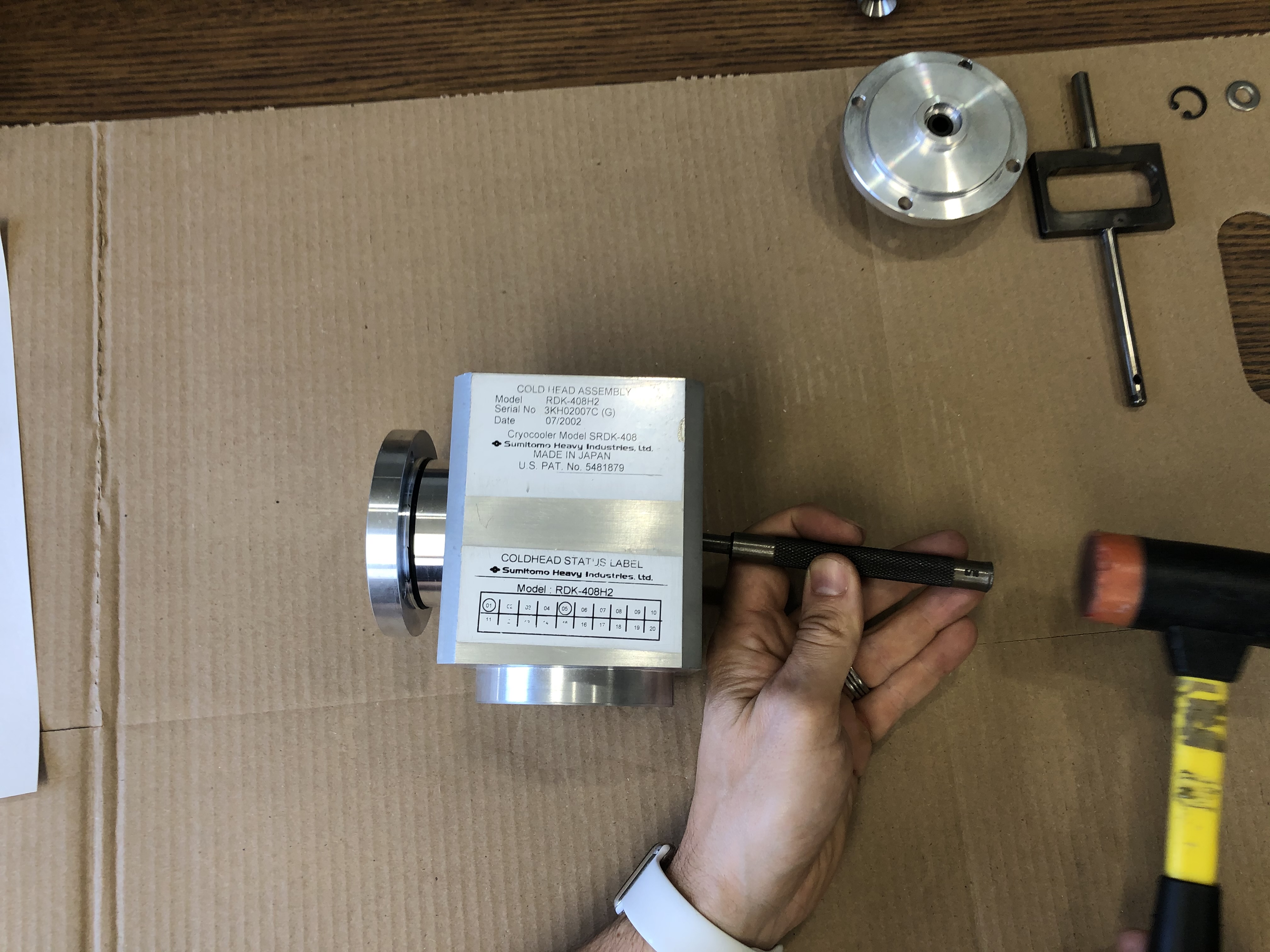
Remove the four M6 fasteners mounting the upper cup to the housing.
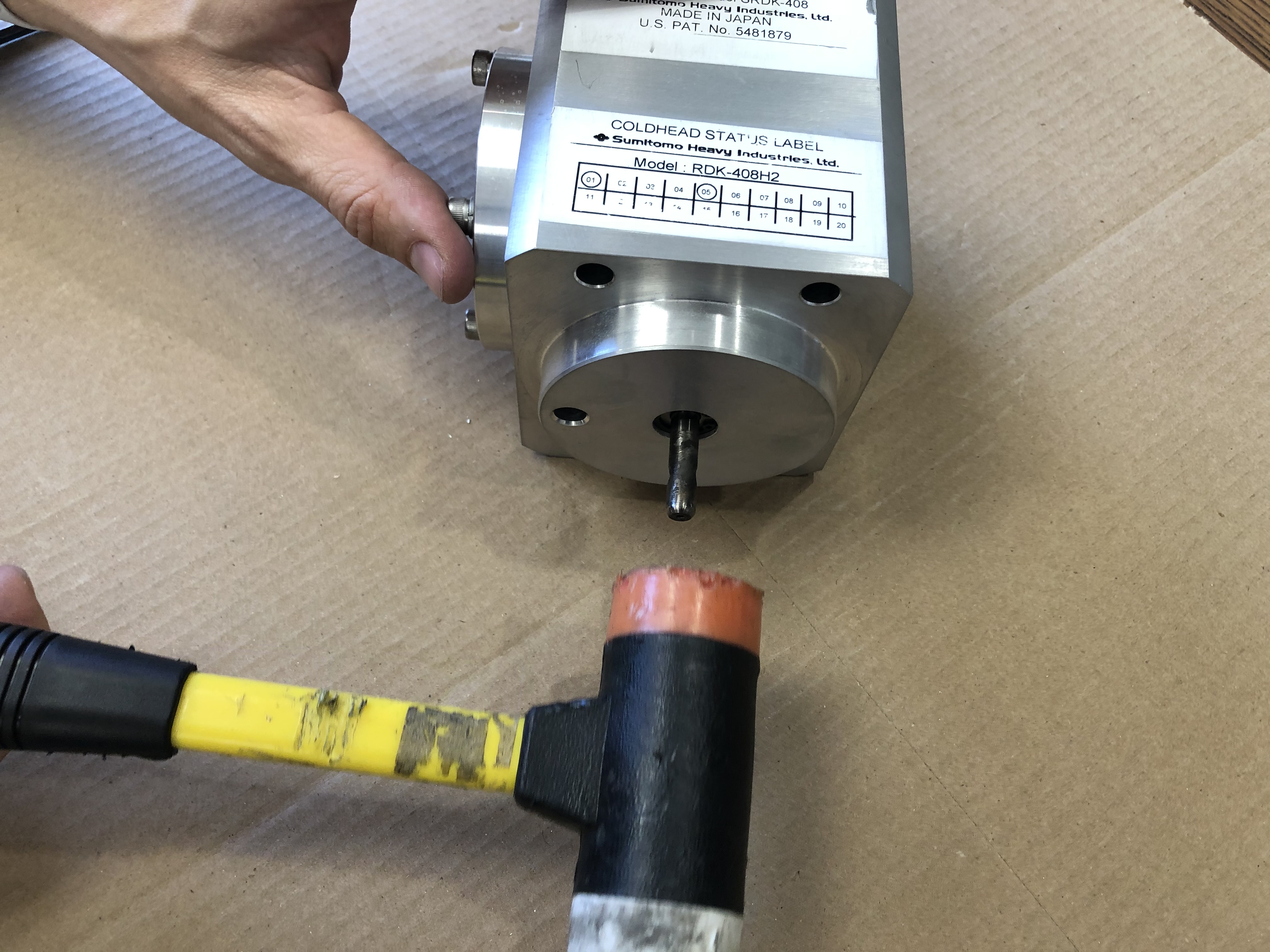
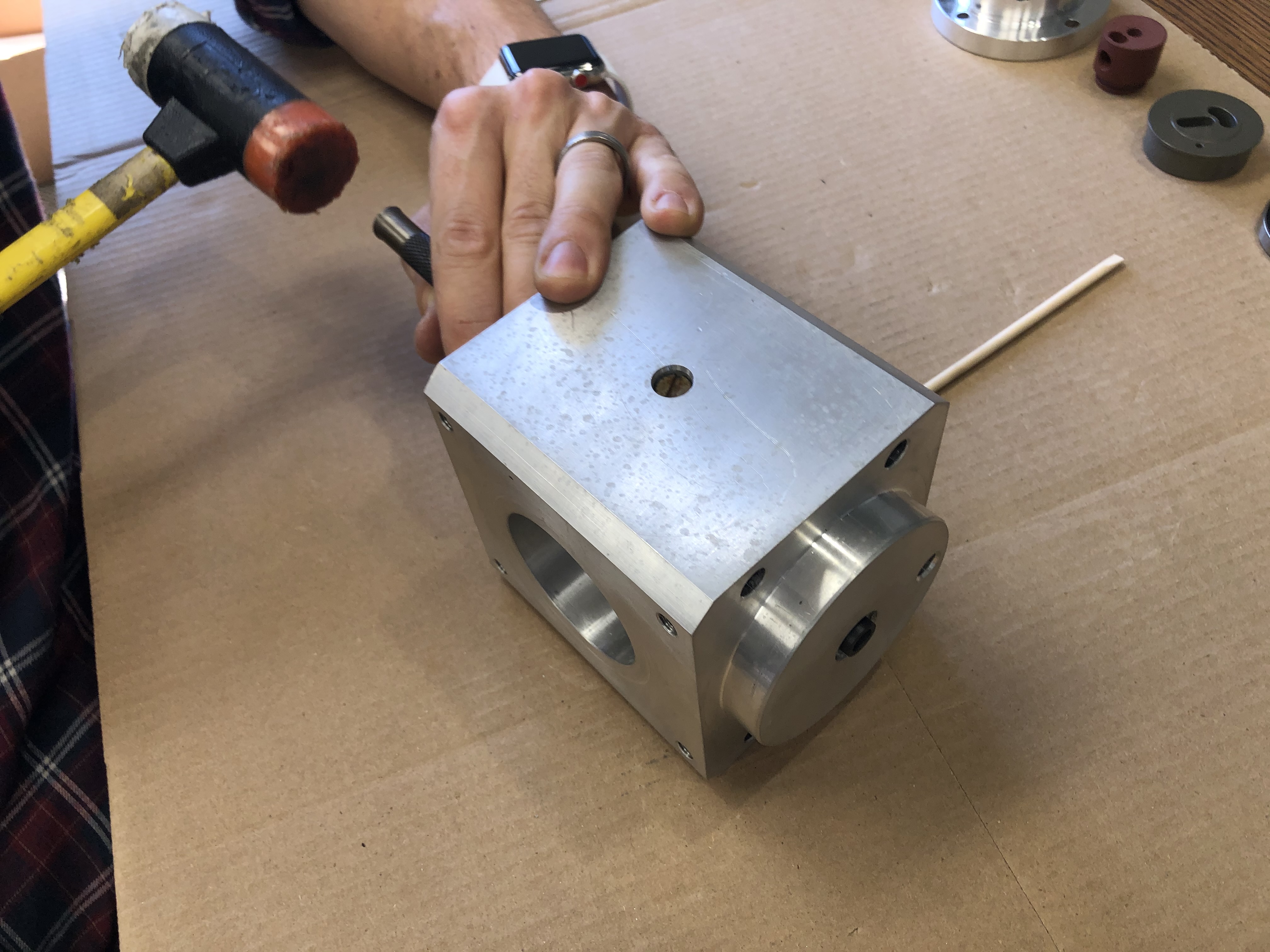
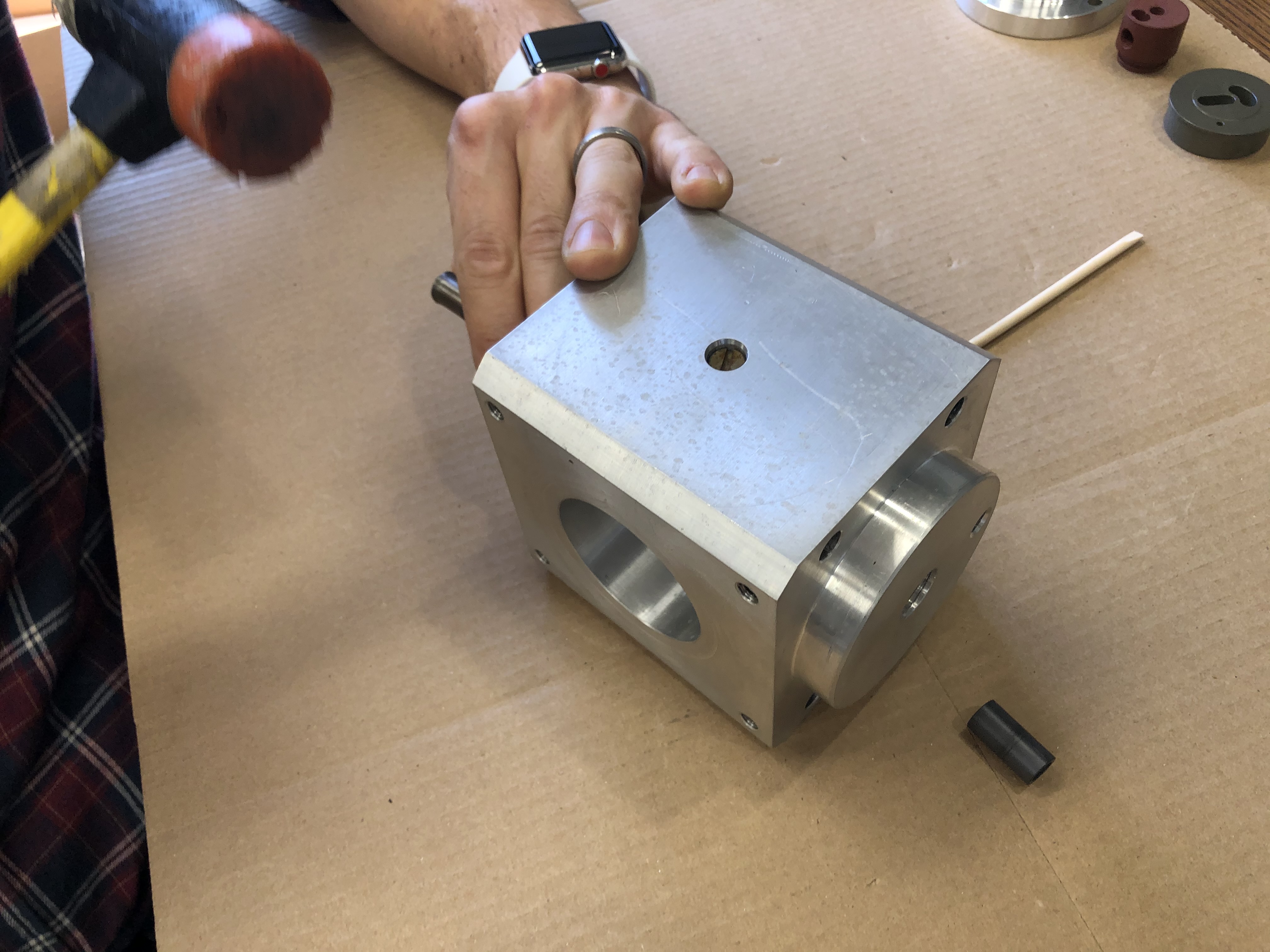
Slide the scotch yoke in all the way until it makes contact with the back of the upper cup assembly. Then, use a mallet to tap the upper cup assembly free from the housing. Keep a hand over the upper cup assembly.
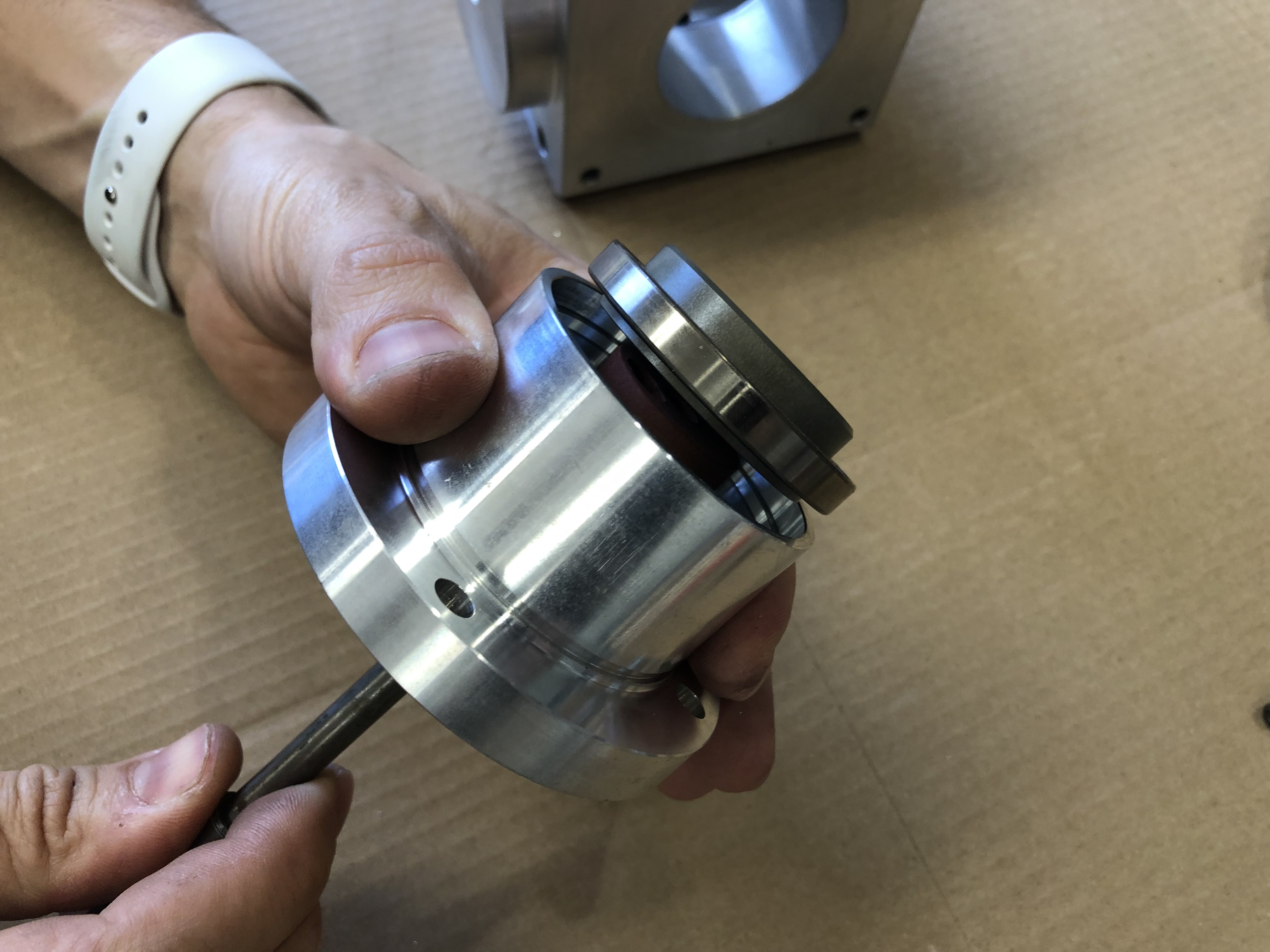
Scotch Yoke Removal
The scotch yoke will come out with the upper cup assembly. It can be removed from the assembly by just sliding it out. The scotch yoke needs to be inspected for straighness as well as stress cracking. It also has a special cleaning instruction
Upper Cup Assembly
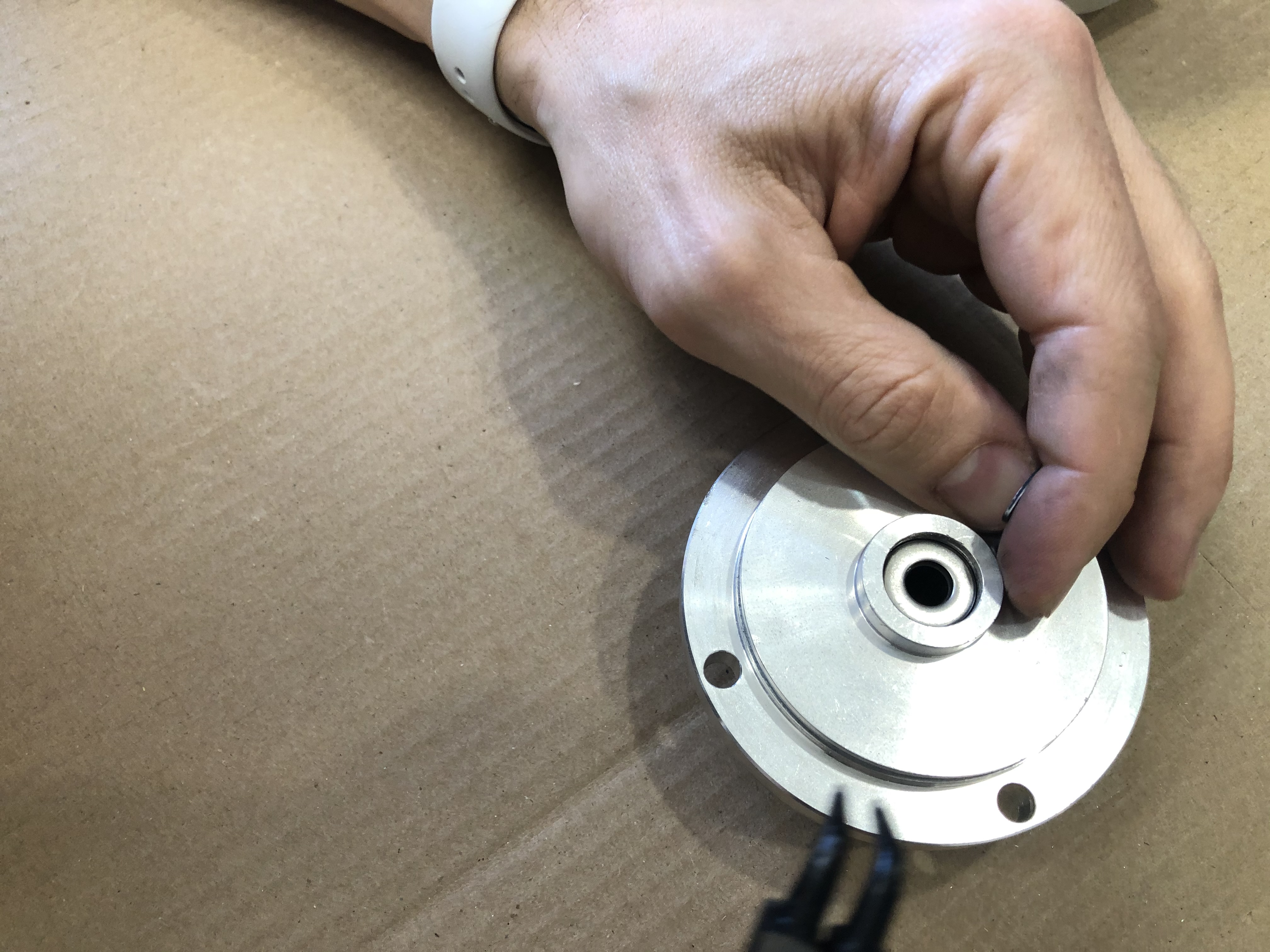
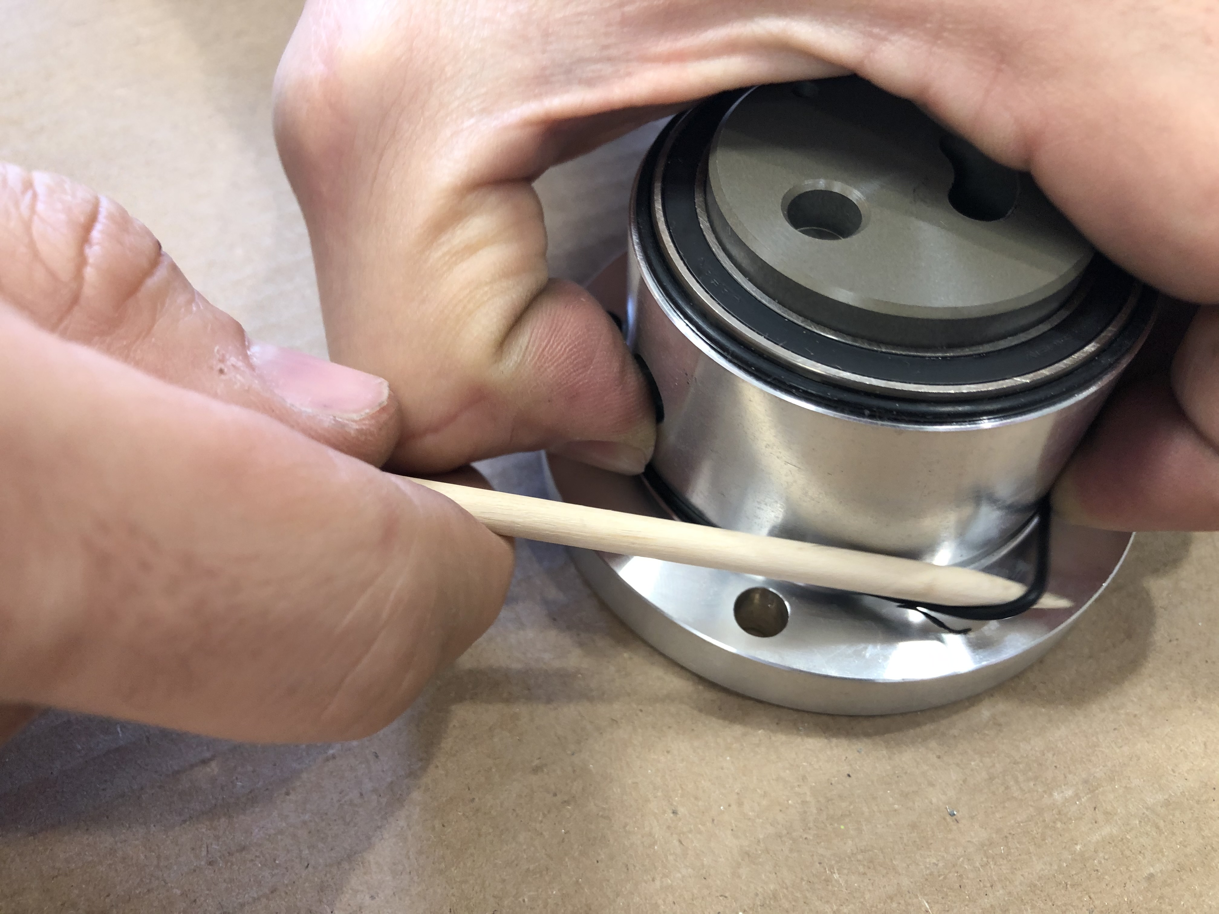
Remove the upper cup assembly to housing o-ring.
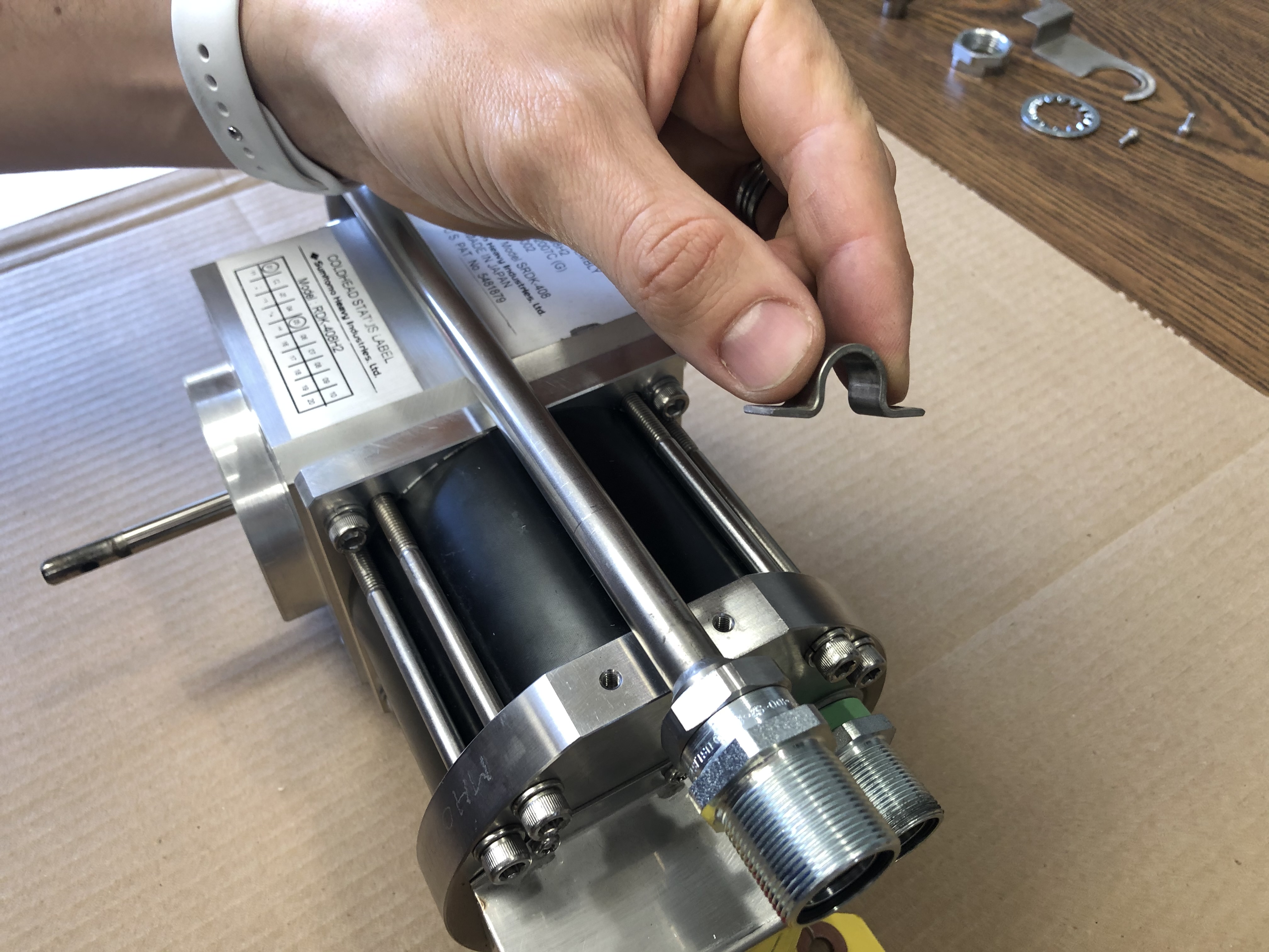
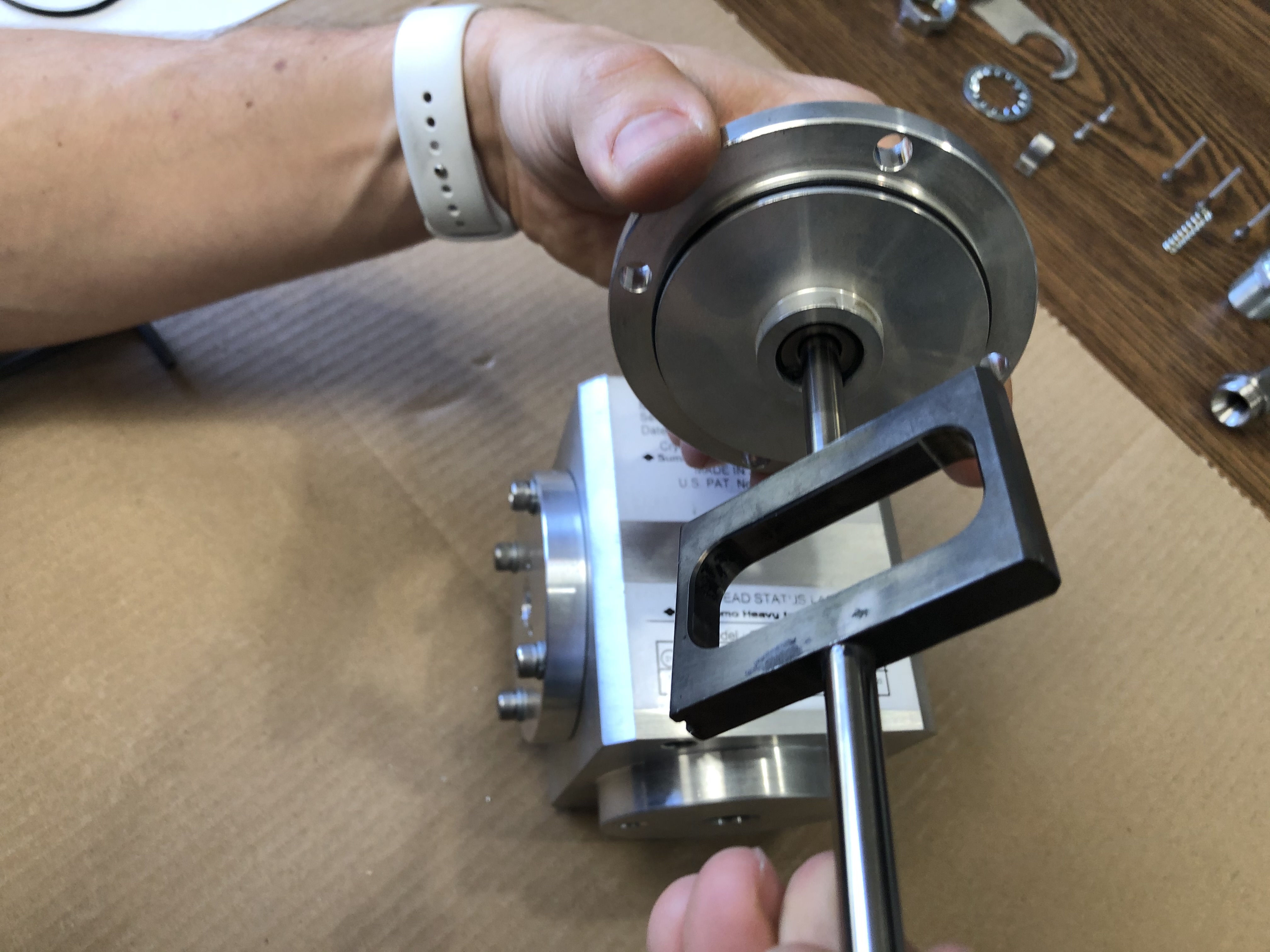
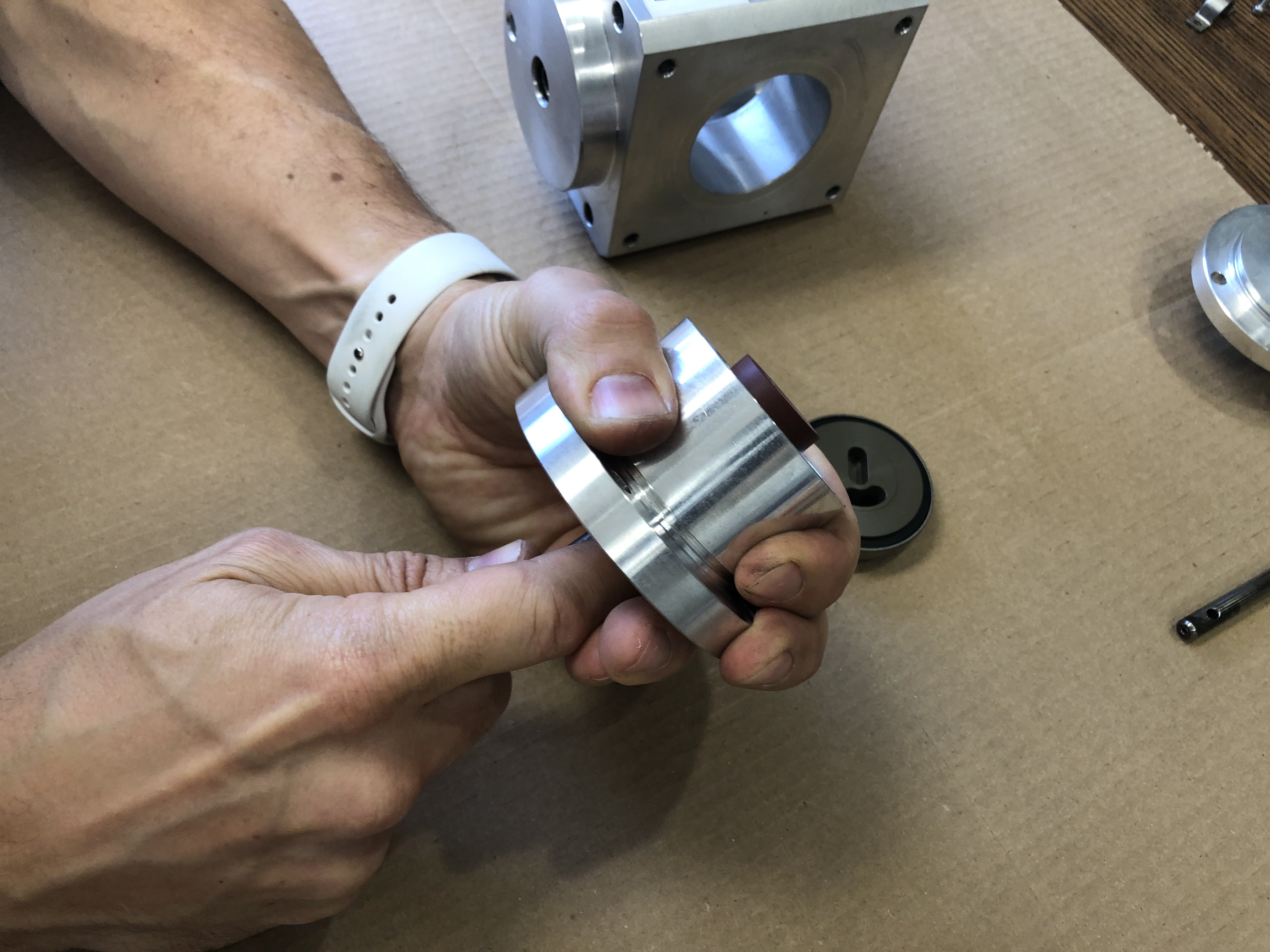
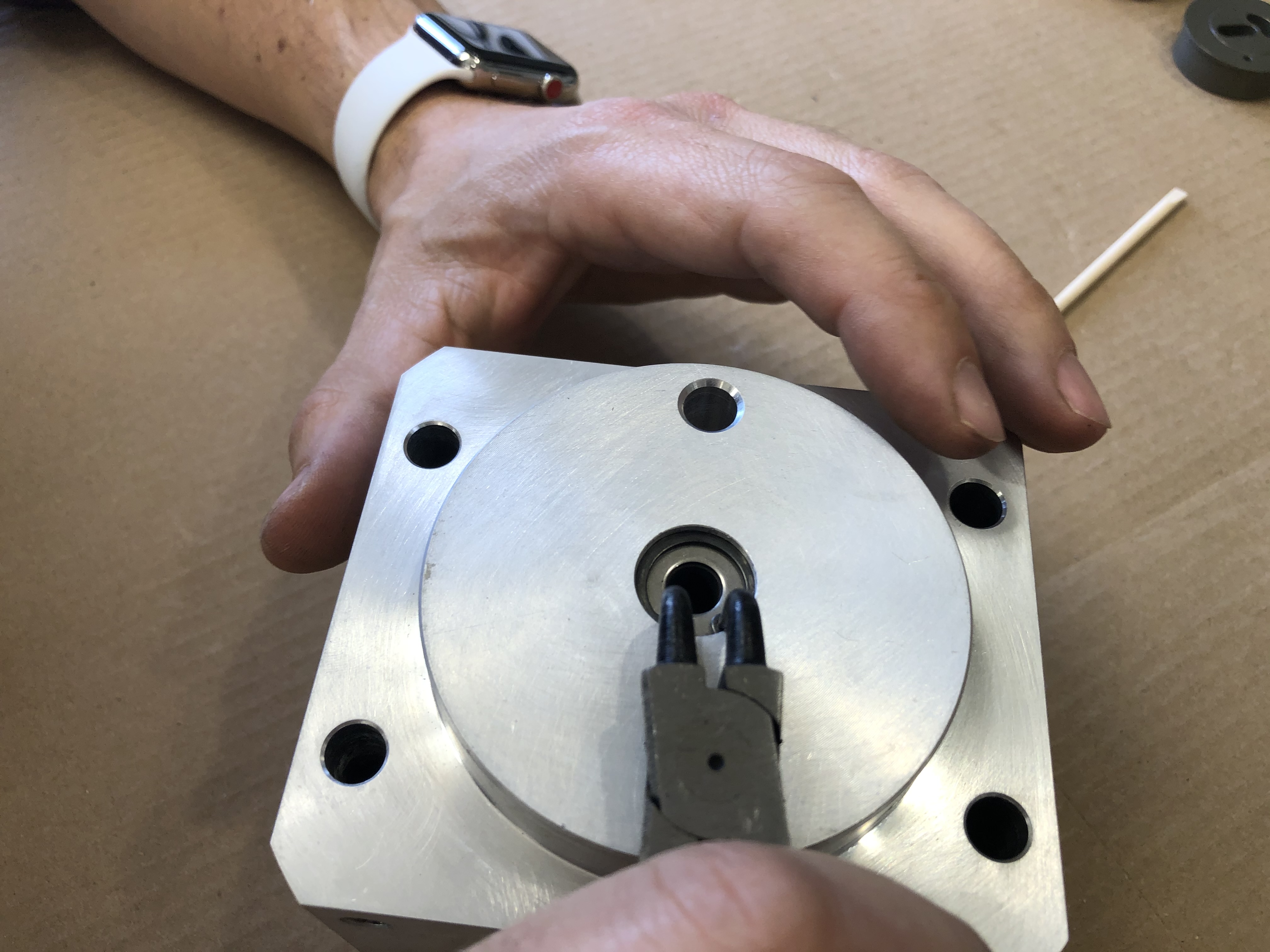
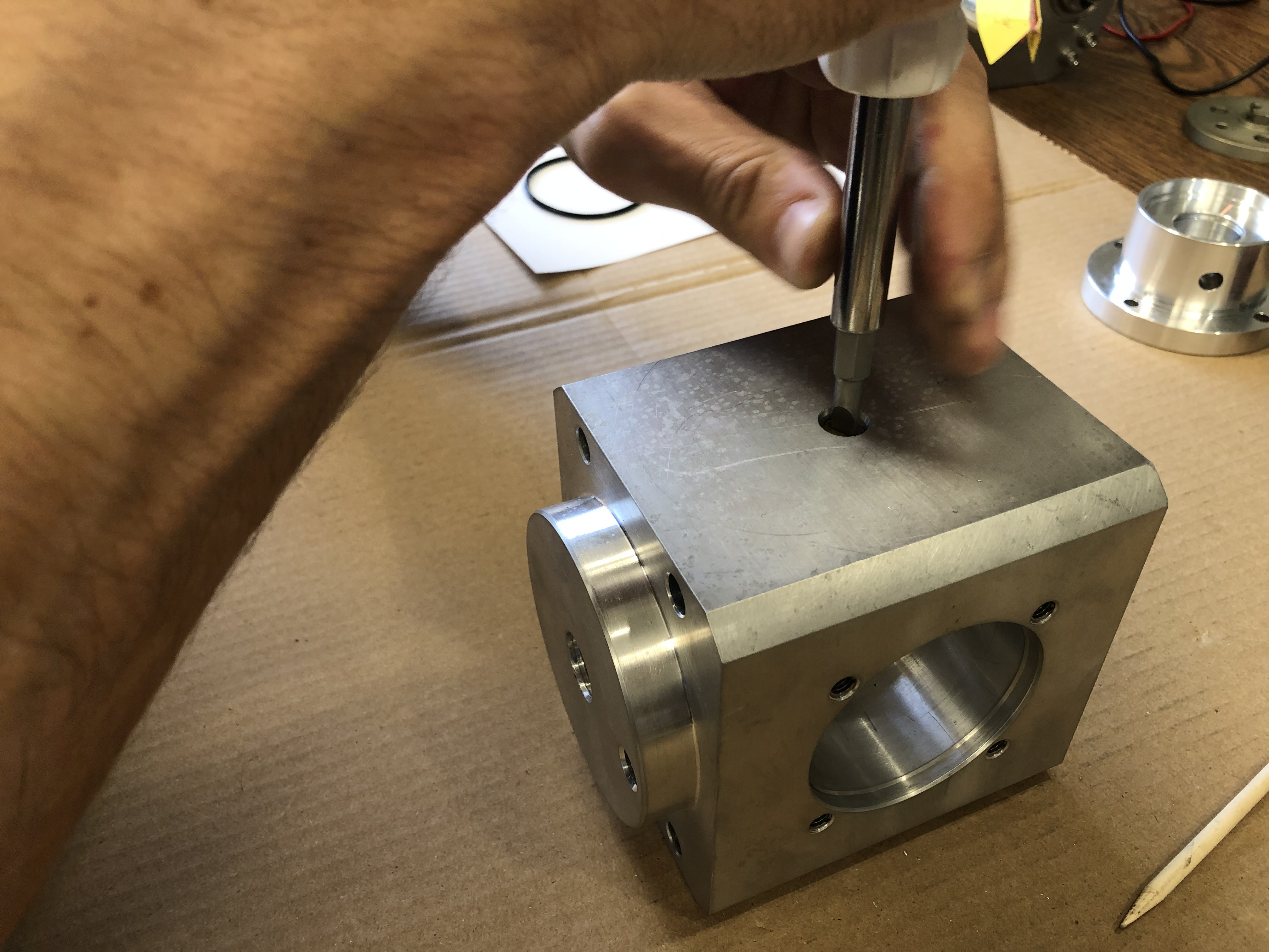
Retaining Ring
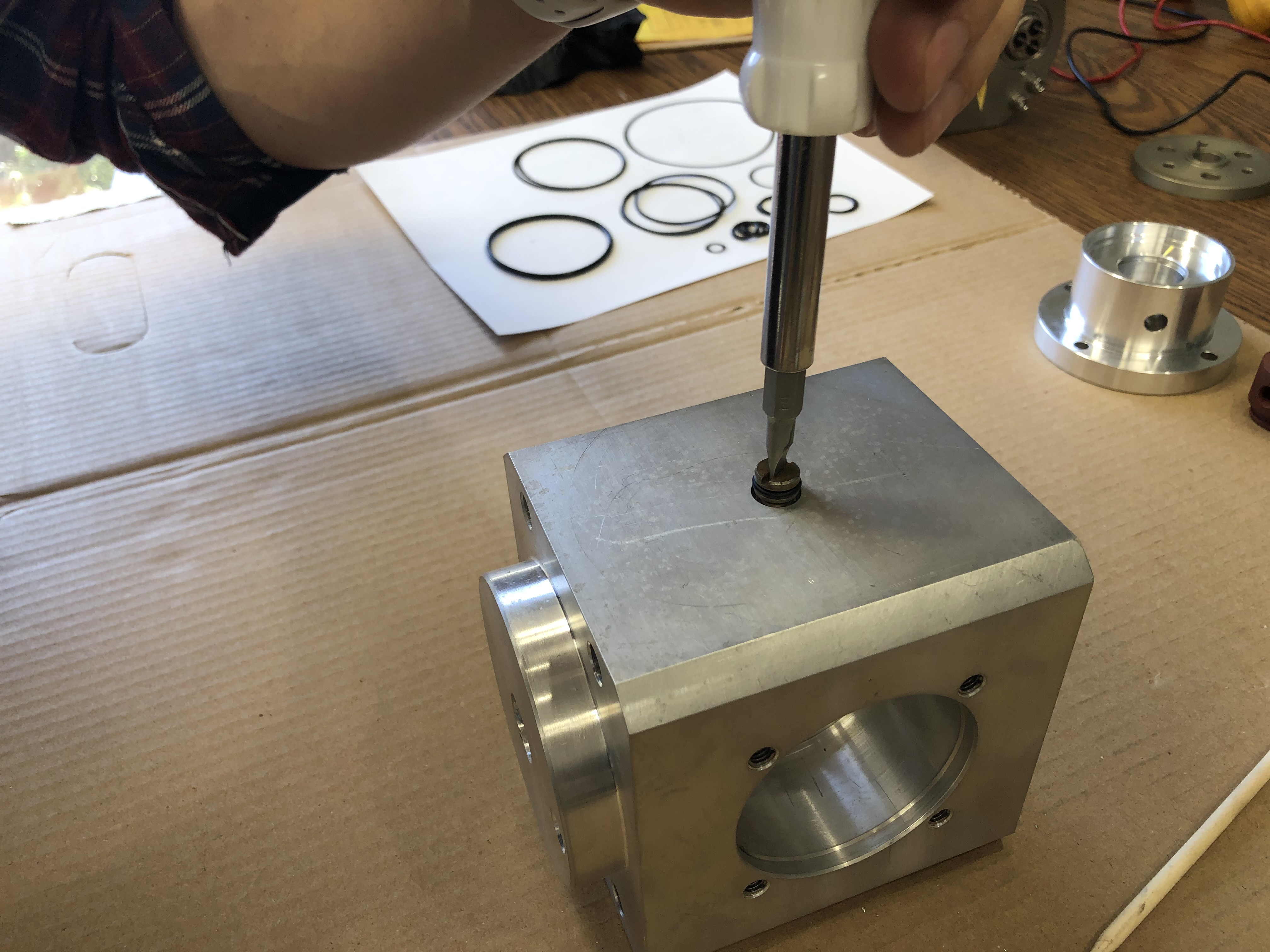
Using the retaining ring pliers, carefully remove the internal retaining ring.
Info
Retaining rings go by a number of colloquial names, the most famous being the "profanity-clip". This name was adopted because of the tremendous speed at which the clip would traval when the clip dislodges off the plier while under load. This typically occurs to technicians without experience with retaining rings and leads to a surprised reaction as well as a profanity.
Remove the retaining washer.
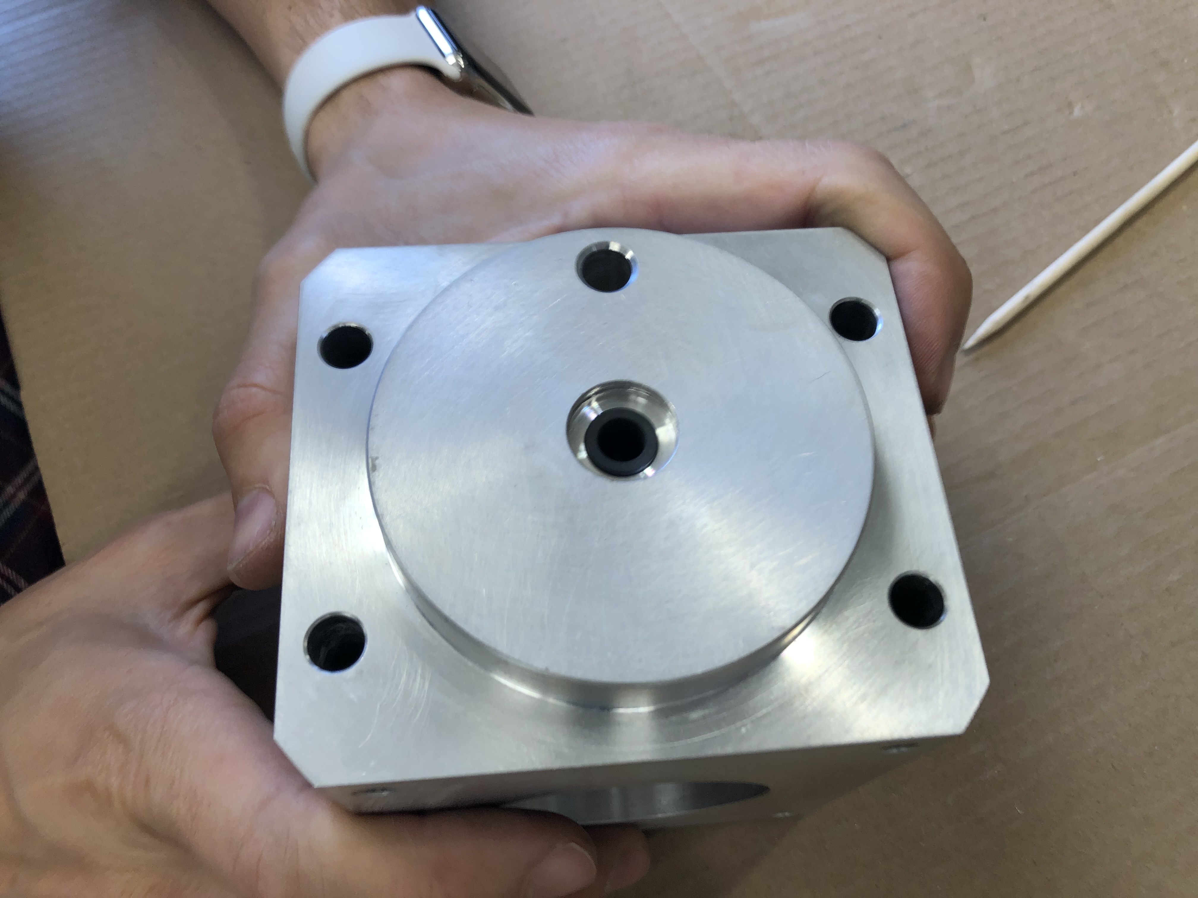
Upper Cup Bushing
Using a pick, remove the scotch yoke bushing from the upper cup.
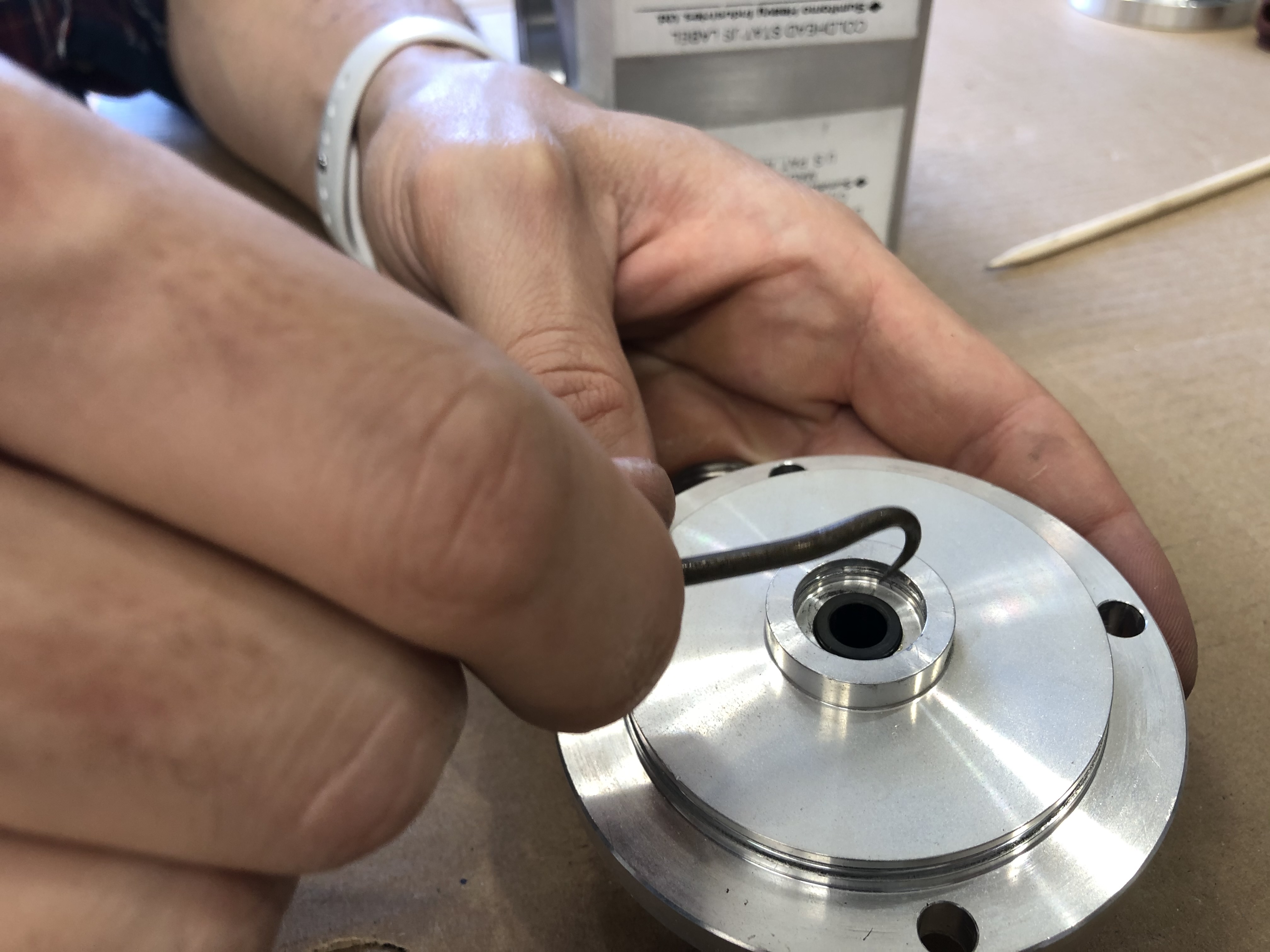
Remove the o-ring inside the up cup bushing hole.
Valve Body Assembly
Loosen the four M6 fasteners mounting the valve body assembly to the housing.
Using a punch or non-marring striking tool and a mallet, reach through the crank case from the motor end of the housing to tap out the valve body assembly.
Control Valve
Remove the valve body to housing o-ring.
Remove the valve body to rotary valve plate bearing o-ring.
Note
The valve body to rotary valve plate bearing o-ring will sometimes fall off inside the housing. Be sure to remove this.
Rotary Valve Plate
Insert a non marring striking tool through the high pressure inlet hole in the valve body to the bottom of the cotrol valve. Use pressure to force the controle valve, rotary valve plate, and rotary valve plate bearing out of the valve body.
Continue pushing until the rotary valve plate and bearing fall free exposing the control valve.
Valve
Continue pushing until the control valve falls free of the valve body.
Note
The valves position is fixed within the valve body from rotating with the rotary valve plate by a pin. This pin tends to be press fit into the valve body but will occassionally come out with the valve. Be sure this isnt discarded or lost.
Be sure that the pin is located and removed.
Note
If the pin is pressed in tight it may be best to keep the pin installed rather than fight to get it out. This might not be ideal if the valve body needs to be cleaned extensively.
Housing
The housing also has a scotch yoke bushing held in with a retaining washer, retaining ring, and a sealing o-ring. The access and removal of the scotch yoke guide bushing is gained in the same way the upper cup assembly is.
Remove the retaining ring and the retaining washer from the housing.
Guide Bushing
To remove the scotch yoke bushing a long punch needs to be inserted thrugh the crank case at the upper cup assembly end from the opposite side of the housing.
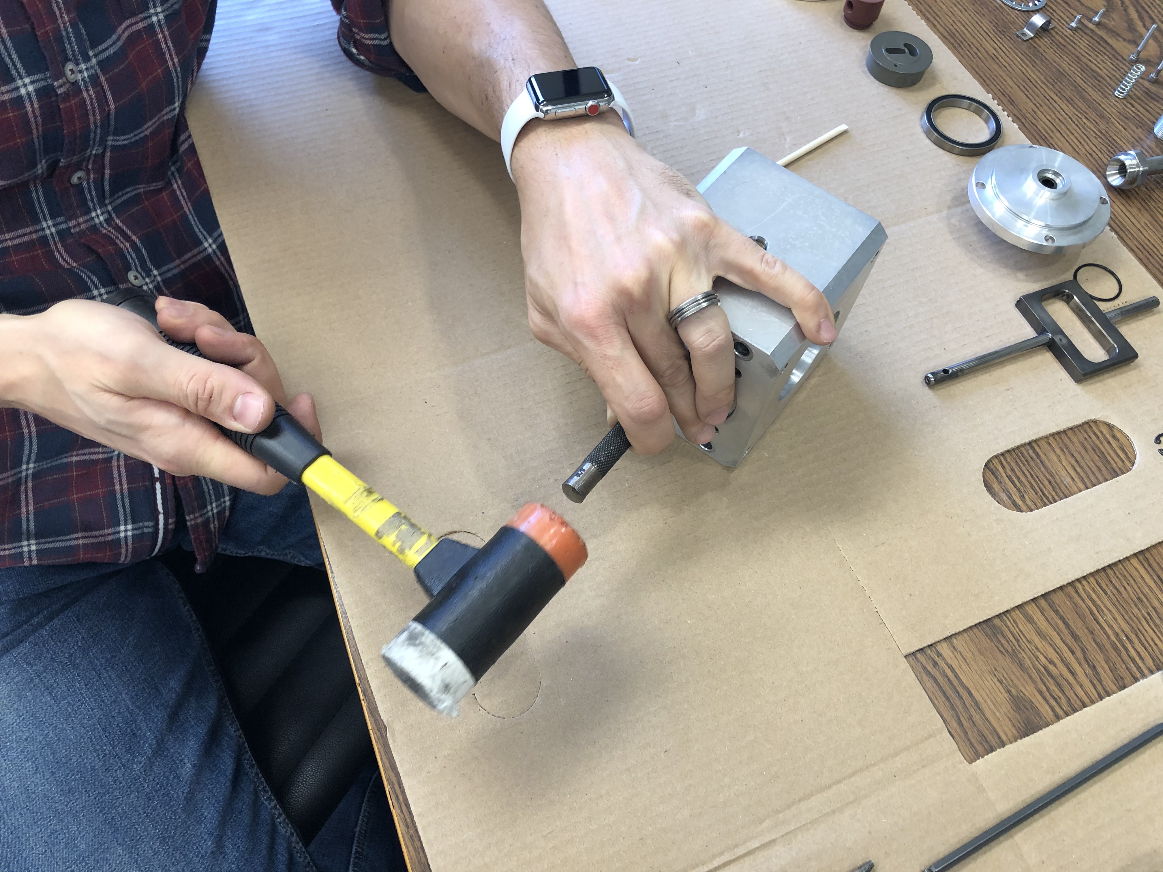
Using a mallet, tap the scotch yoke guide bushing free from the housing.
Scotch Yoke Guide Screw
The scotch yoke guide screw is a fastener that is used to keep the scotch yoke from twisting and rubbing against the housing. The point of the fastener is designed to fit into the groove on the edge of the scotch yoke. This groove is only on one side of the scotch yoke making it directional.
Warning
Adjustment or installation of the scotch yoke guide screw can damage the scotch yoke if the groove is not properly aligned with the screw point. Adjustments and installation of the scotch yoke guide screw must be done slowly and softly ensuring that there is no binding between the two.
Using a large 7/16 flat head screwdriver, remove the scotch yoke guide bushing from the housing.
Once the scotch yoke guide screw is free from the housing, remove the oring that holds it together.
Success
The teardown portion of the Sumitomo Gen 2 refurbishment work instructions is complete.