Motor Refurbishment
Electrical Pre-Check
Connect the drive cable connector from the motor windings tester to the motor. Then connect the cable on the tester to the top plug and place the selector to A/OL. Connect the multimeter to the motor windings tester.
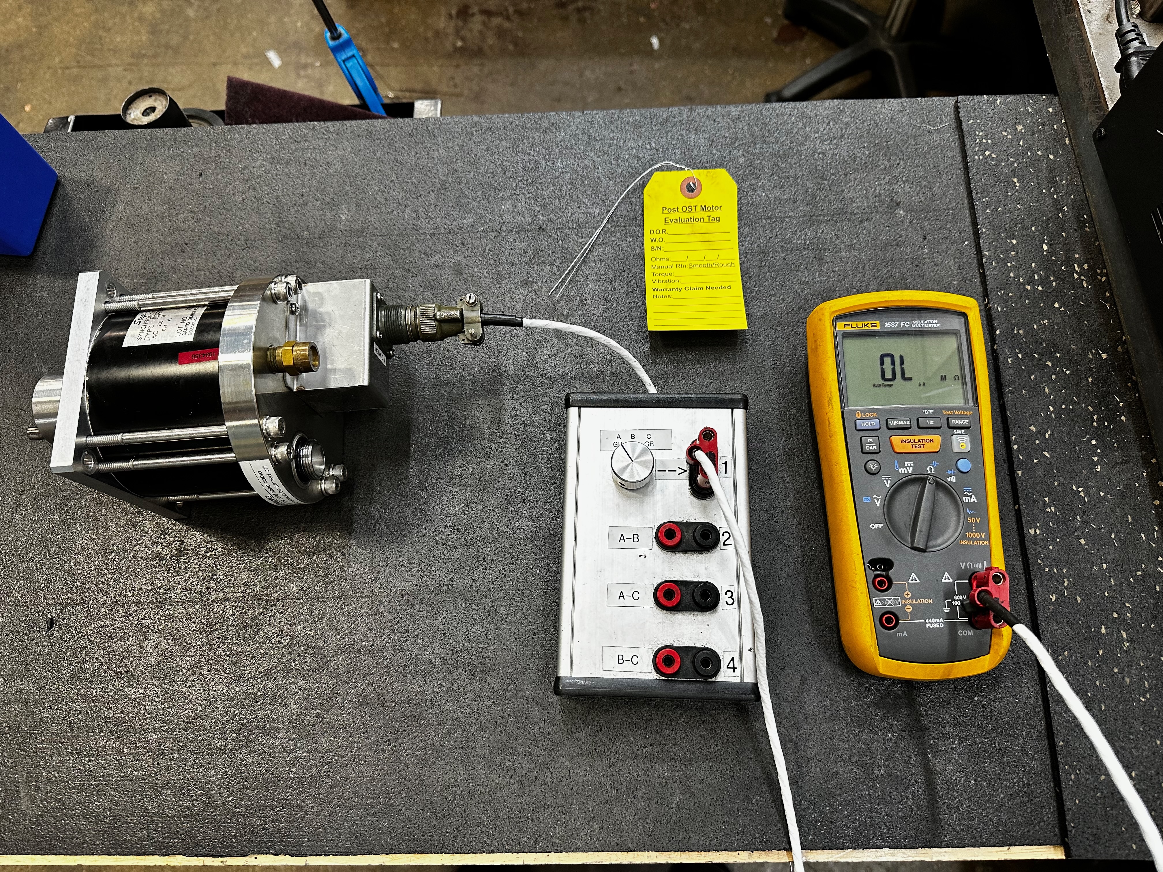
Set the multimeter to the Ohm setting.
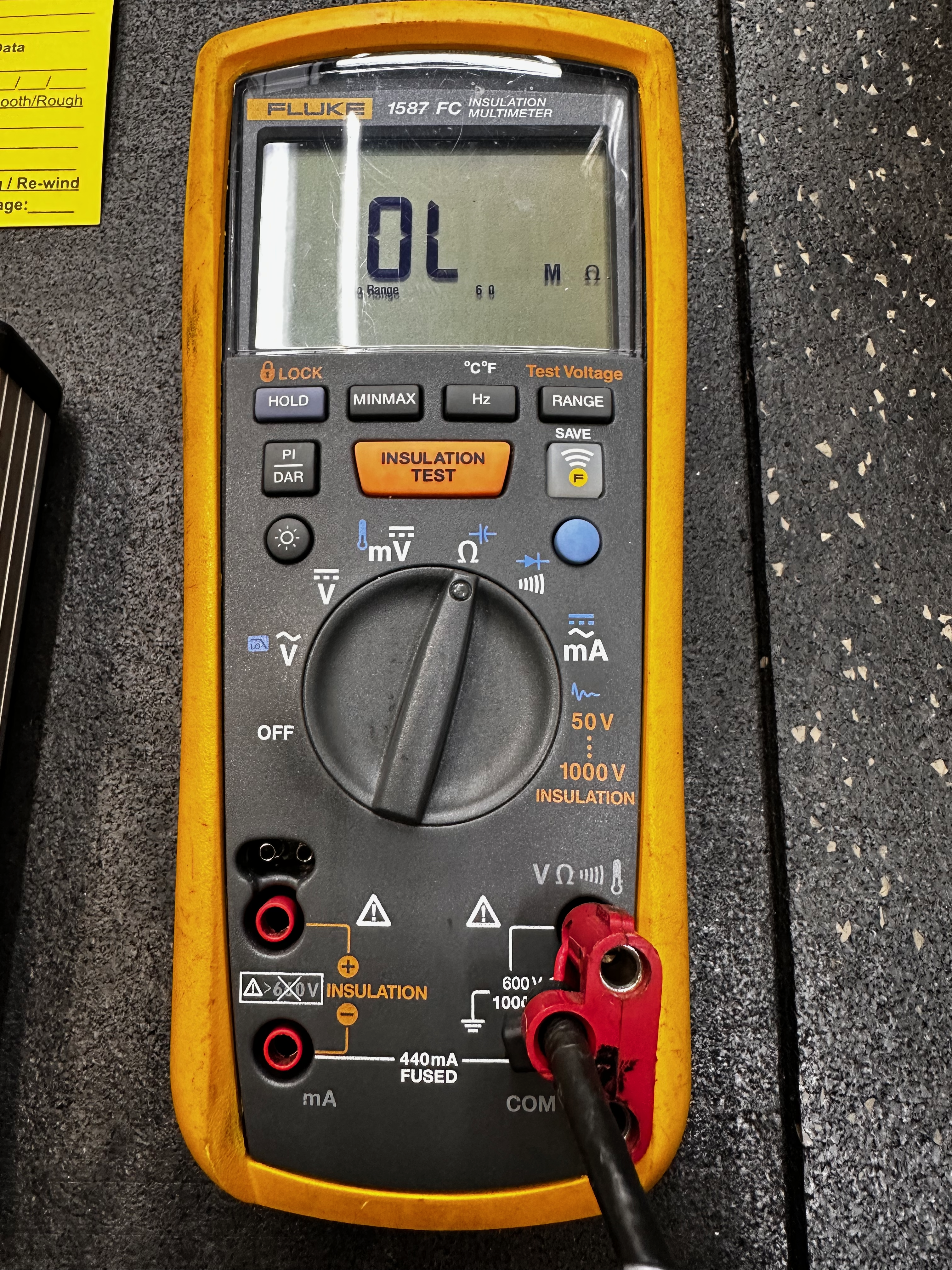
Resistance A to Ground = O.L. A-B, A-C, A-D = 242-260 and ± 2 ohms between each leg.
| PINS | A | B | C | gnd |
|---|---|---|---|---|
| A | NA | 242-260 | 242-260 | OL |
| B | 242-260 | NA | 242-260 | OL |
| C | 242-260 | 242-260 | NA | OL |
| gnd | OL | OL | OL | NA |
Rotor Check
Check if Rotor is True
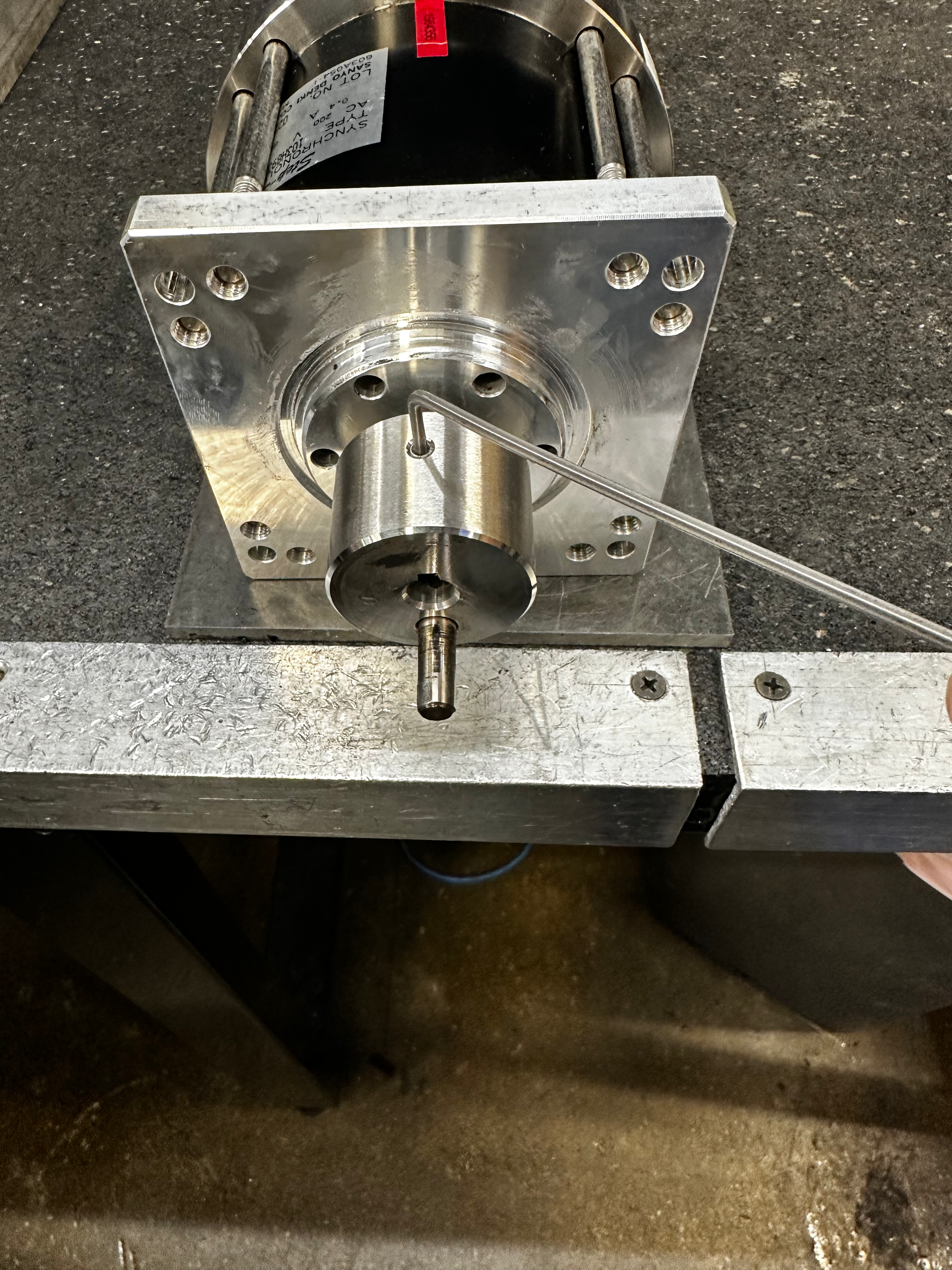
Install the crank to the front plate gauge and power the motor observing the gauge movement.
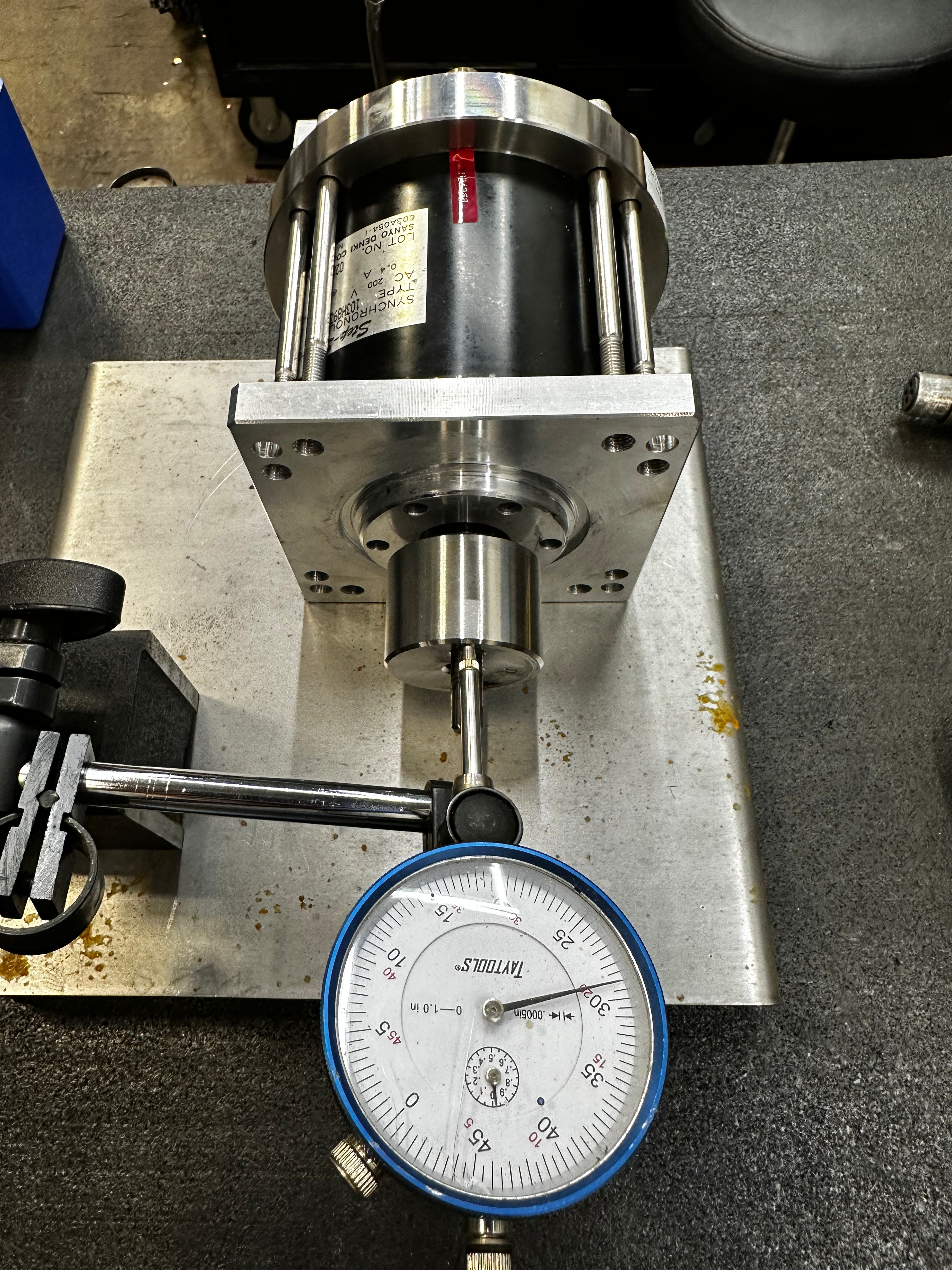
Be sure that the indicator arm is clear of the crank pin.
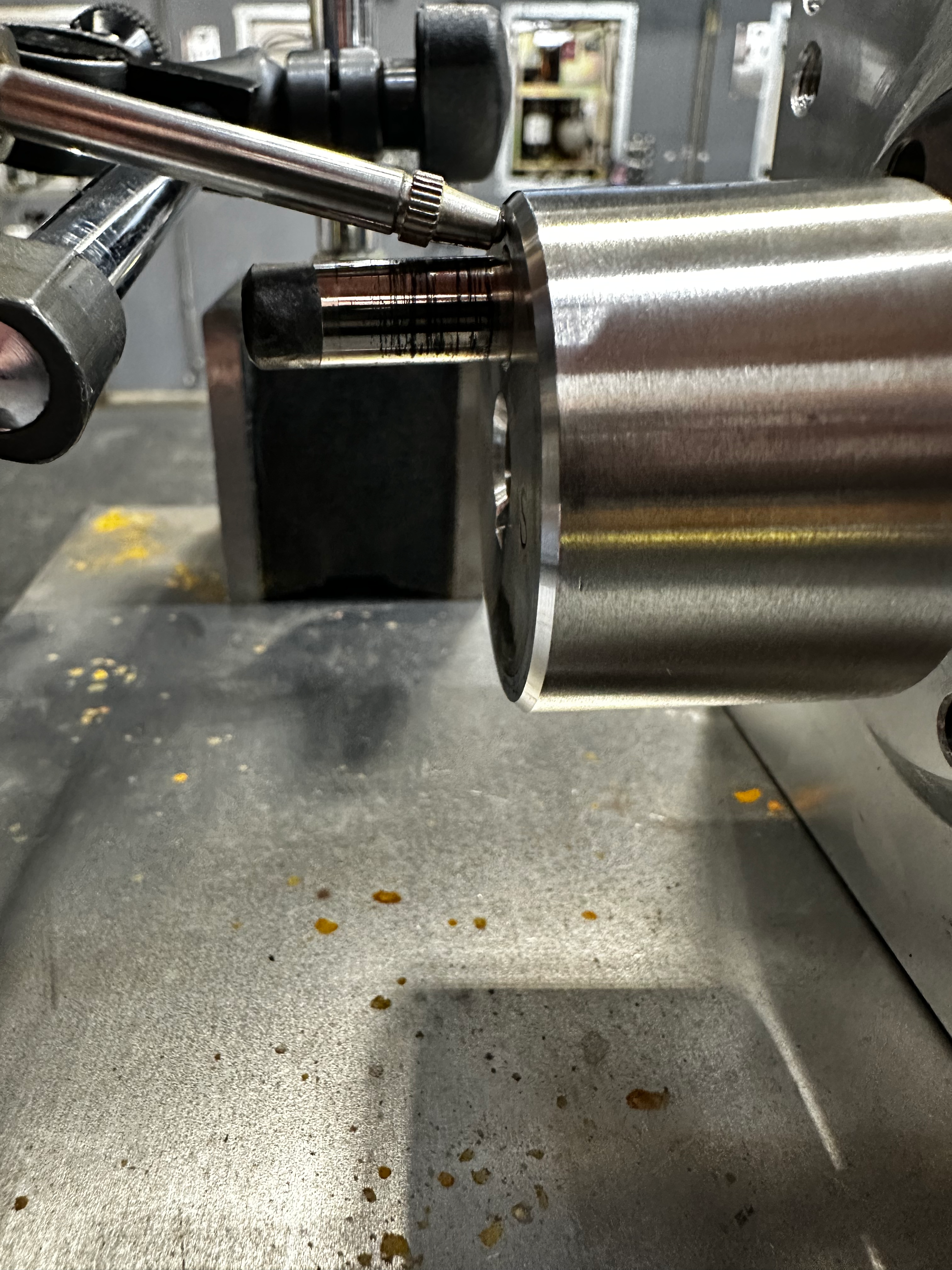
Once positioned correctly lock the dial indicator into place.

If the crank is not straight (the indicator needle is swaying) proceed to Straightening The Rotor. If straight, proceed to Remove Used Motor Crank.
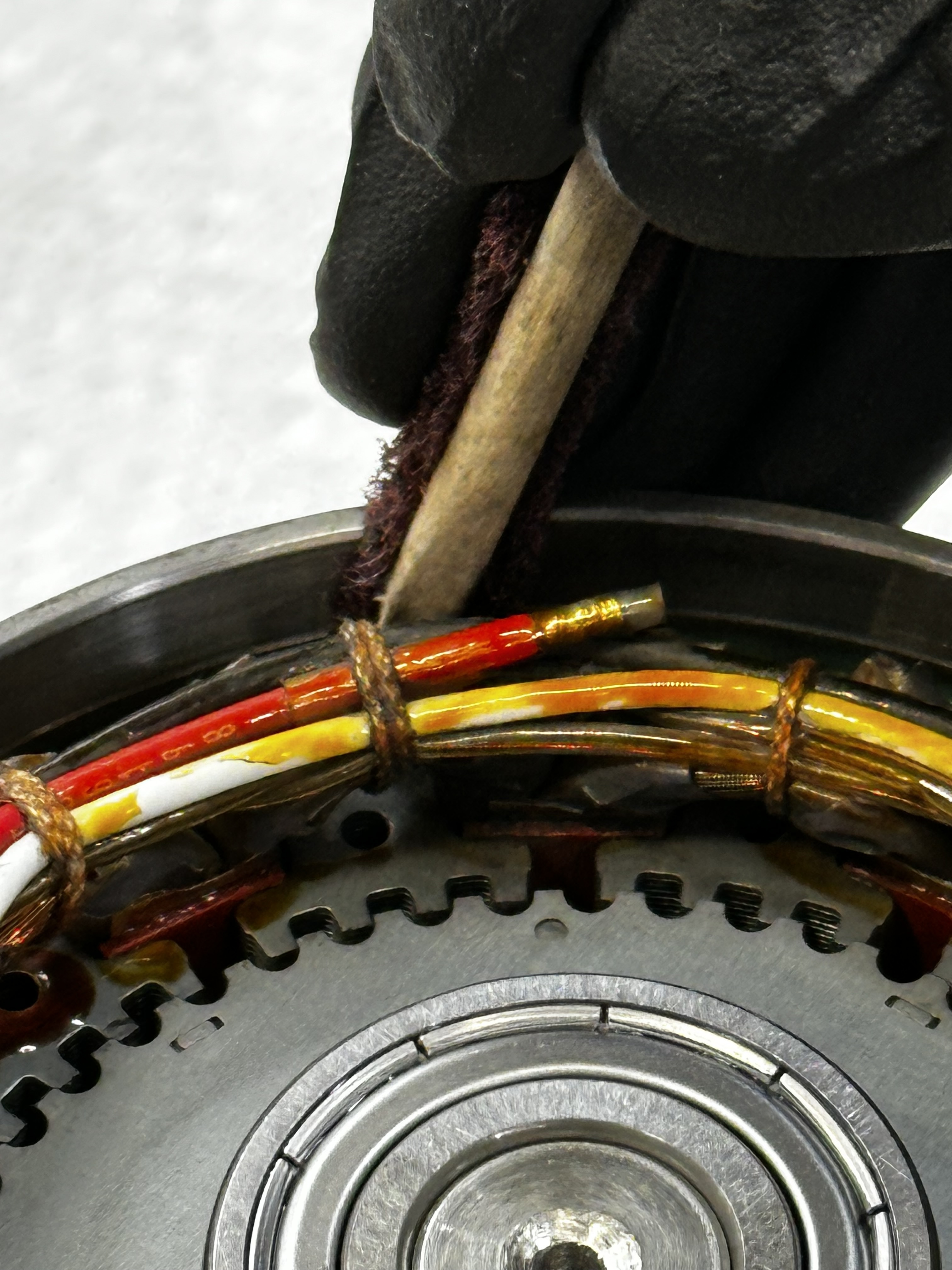
Straighten Rotor
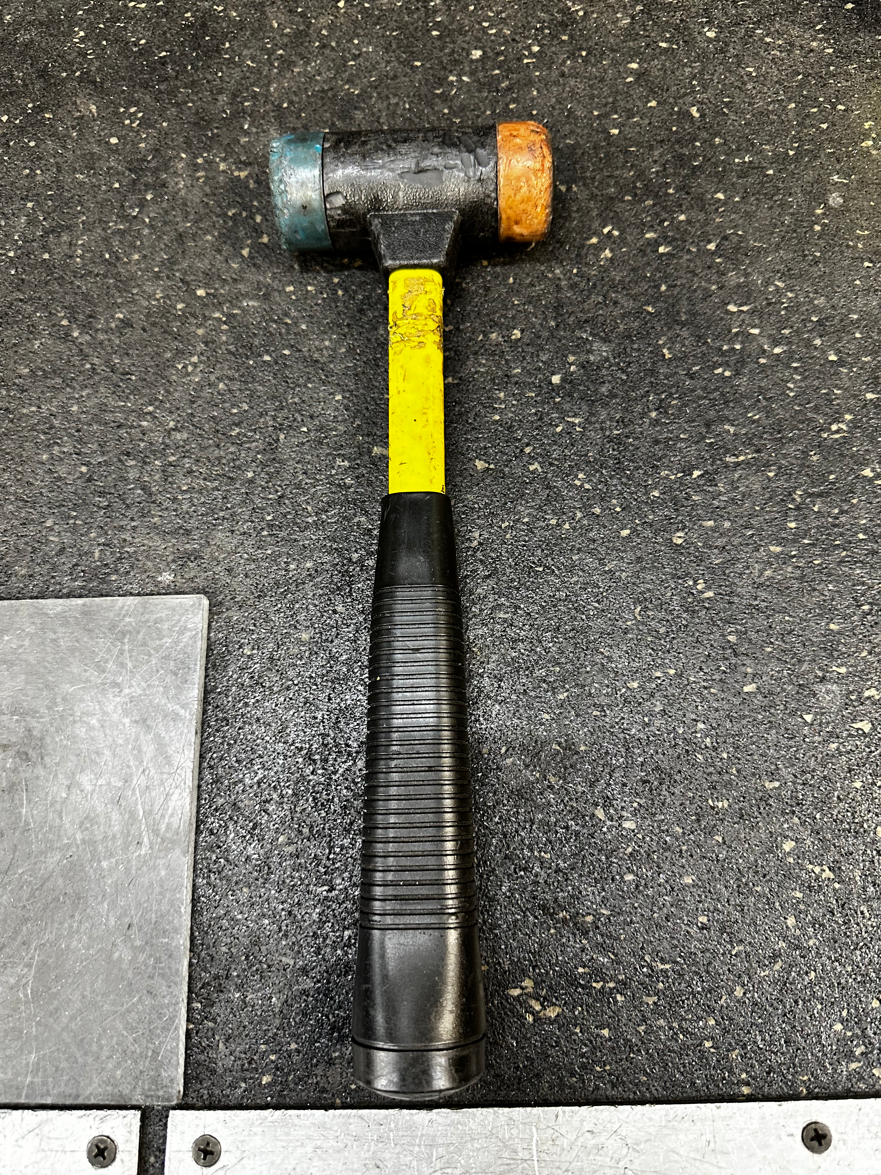
When the gauge indicates the crank is orientated to the high spot use the mallet to tap downward on the crank.
The crank is at a high spot when gauge needle sways to a HIGHER number.

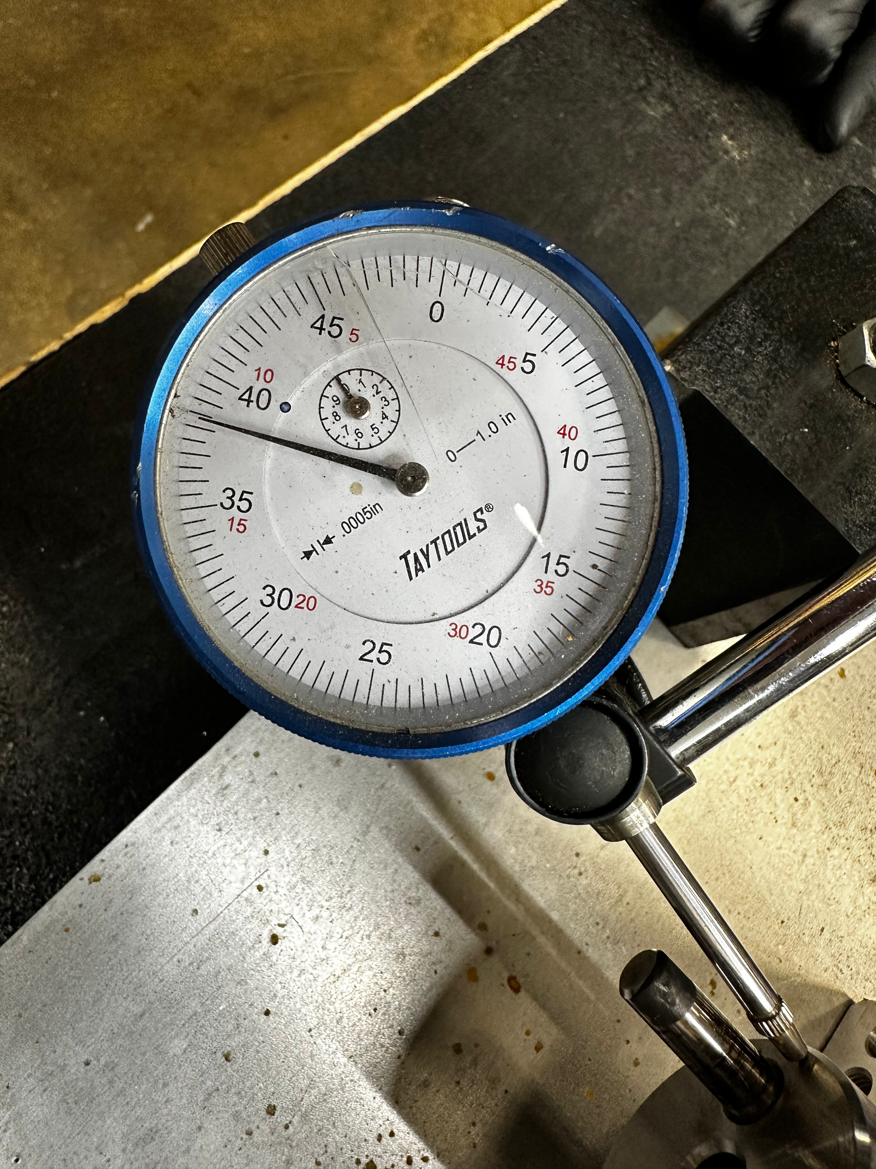
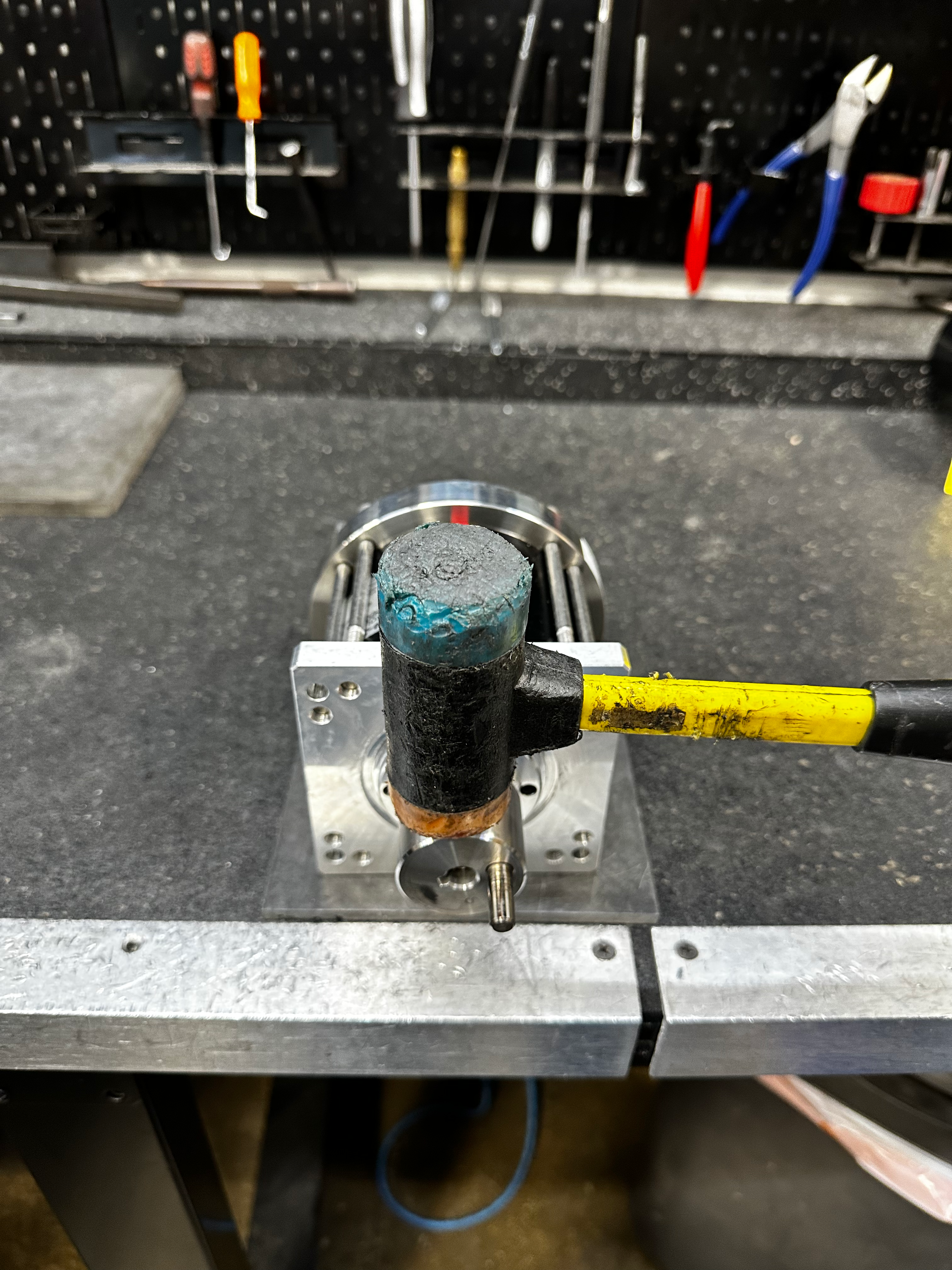
Rotate the crank and check for swaying on the gauge. If there is still swaying then repeat the Straightening The Rotor process until there is no more swaying.
Remove used motor crank
Warning
Only use non ball-end hex keys. Ball-end hex keys increase the risk of stripping the hex socket.
Warning
Apply light pressure to avoid stripping out the hex socket. L
Warning
Loctite may be present and a heat gun will be required before the screw can be removed with light pressure.
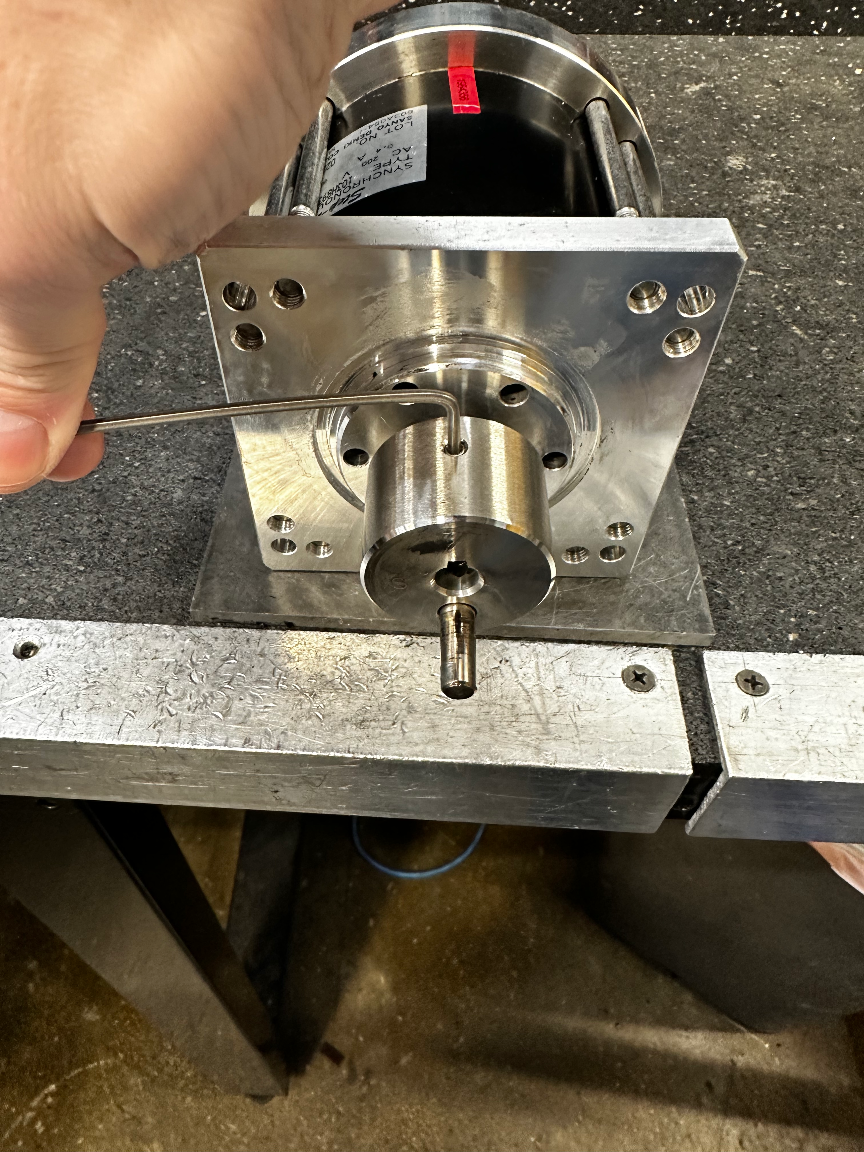
Remove the motor set screw with a 2.5mm hex L-key.
Warning
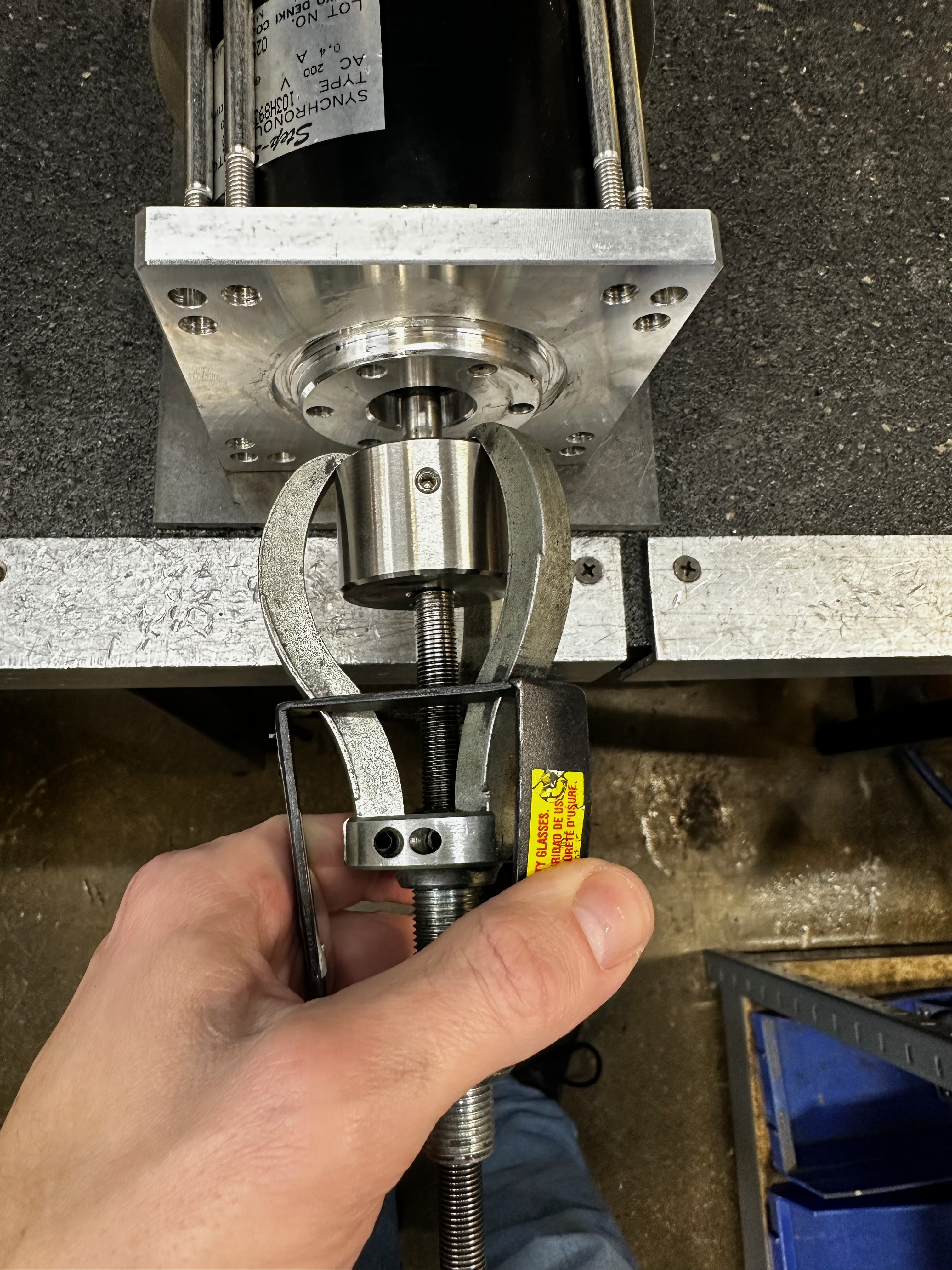
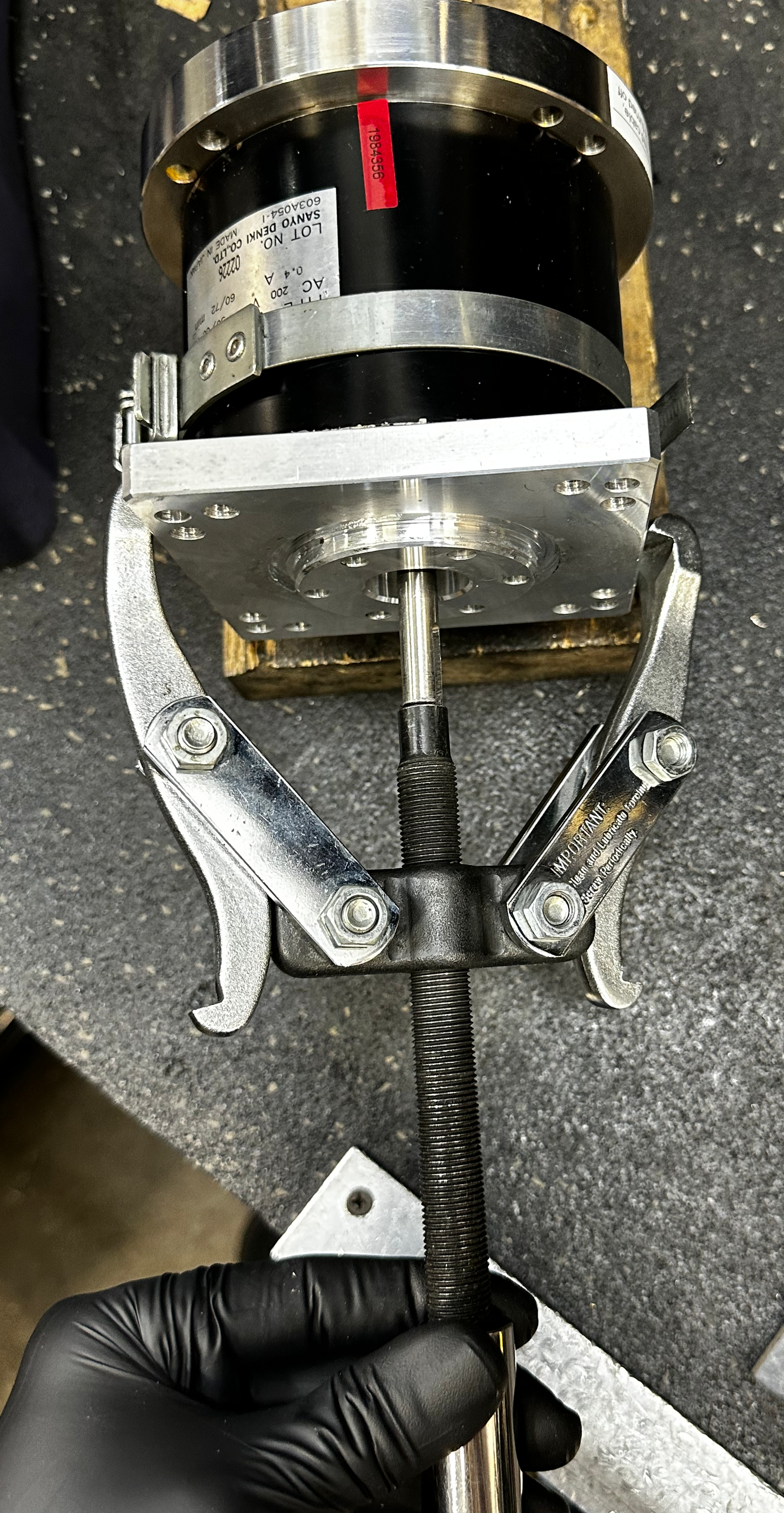
The 3 jaw puller may be required to remove the crank in order to not damage the shaft of the rotor.
Pull the crank off by hand or use the 3 jaw puller if needed.
Remove Power Receptacle
Remove Cover Screws
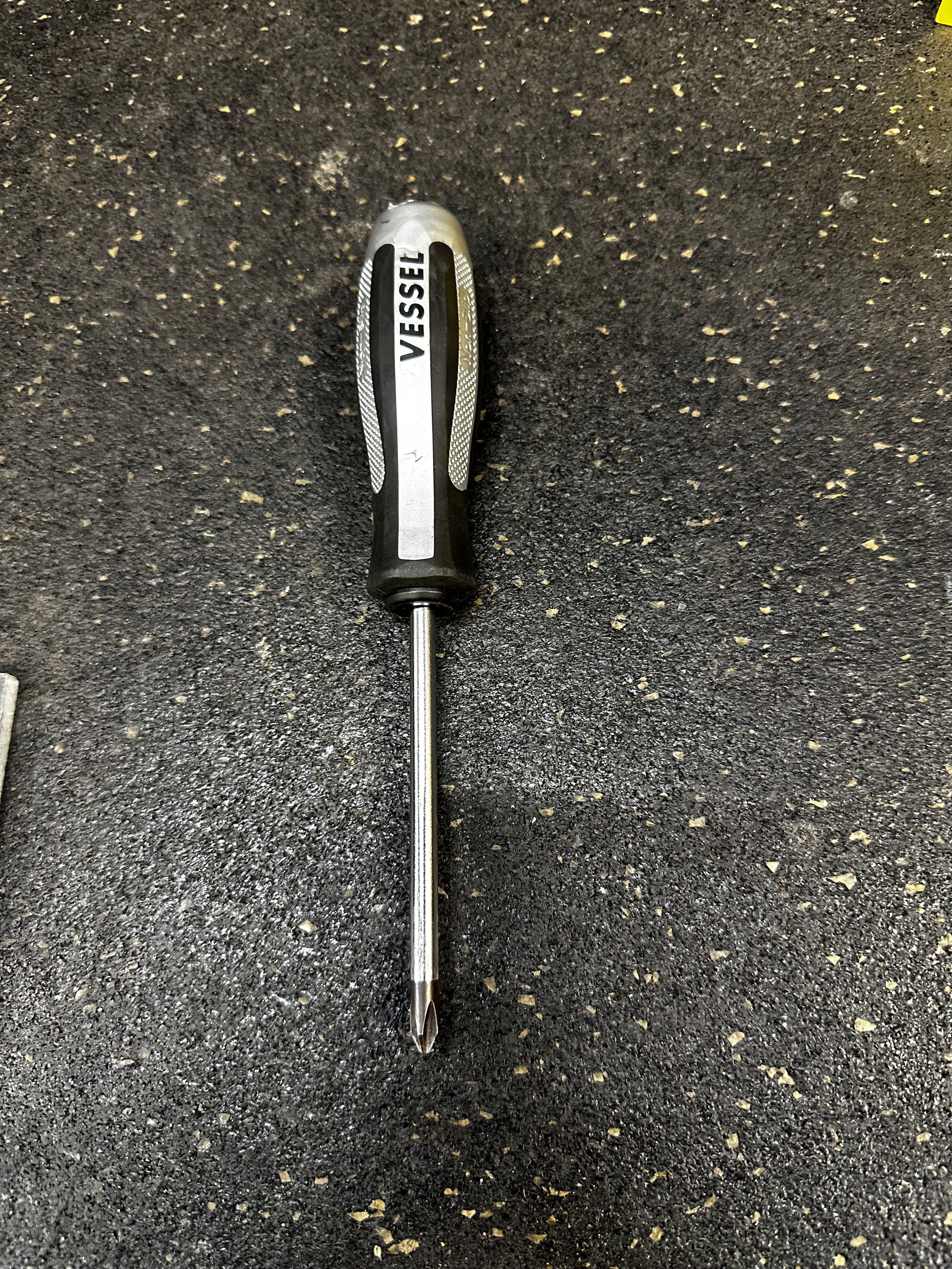
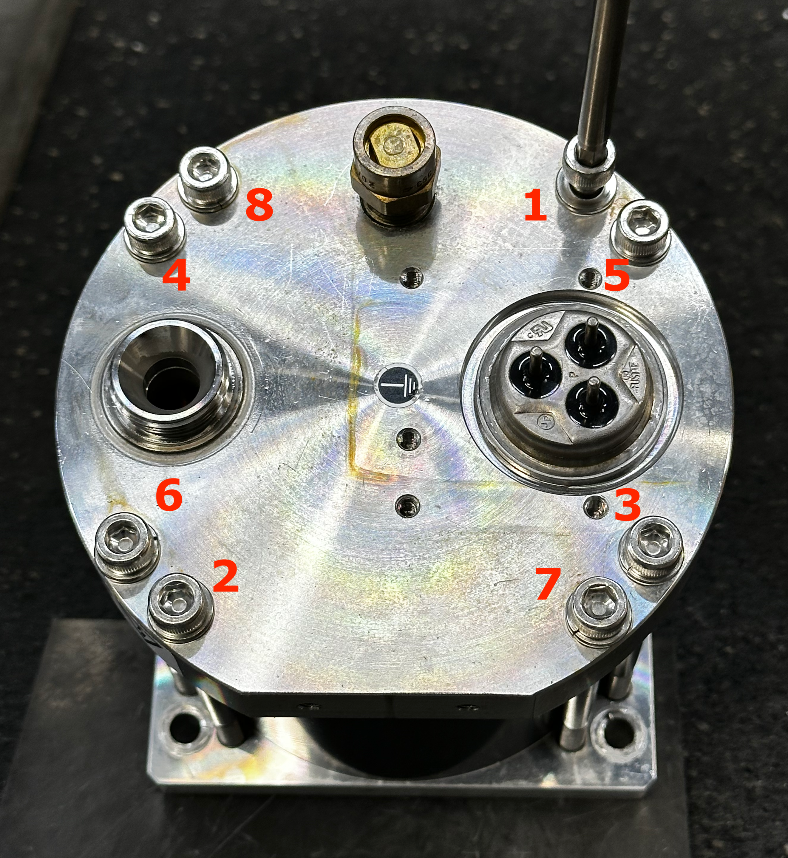
Remove the 4 x JIS # 2 screws from motor receptacle exposing the terminal connectors and ground wire.
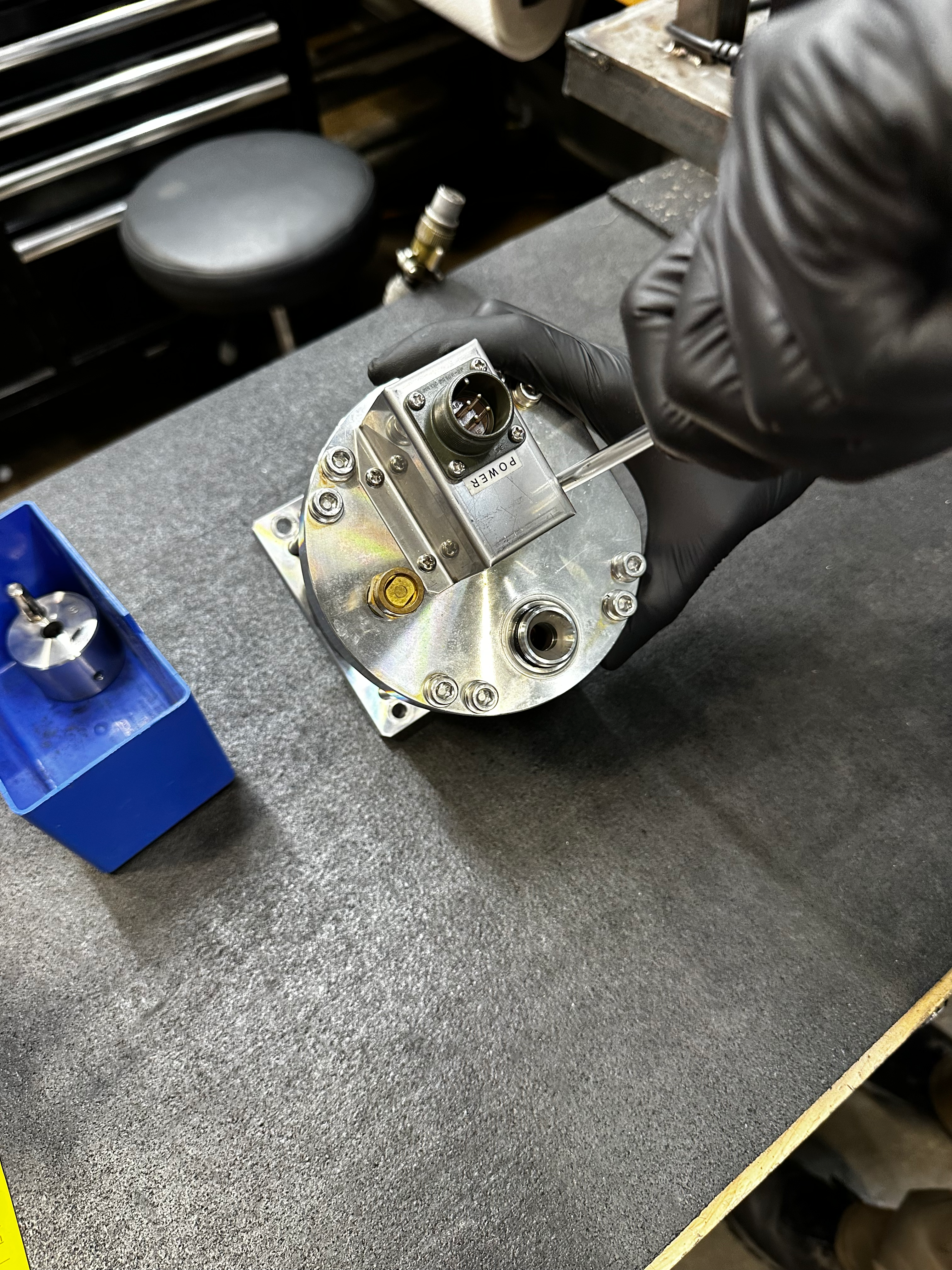
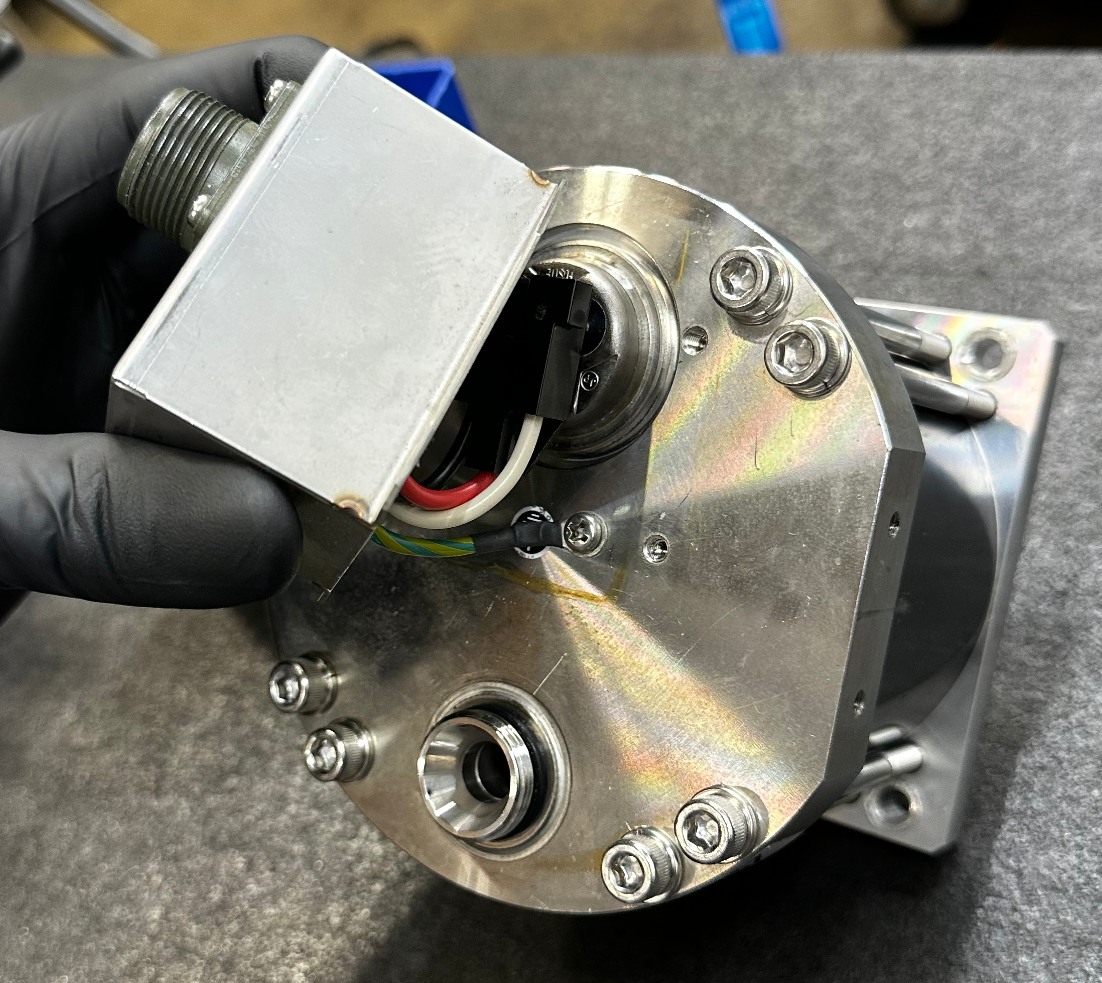
Disconnect Ground Wire
Remove the 1 x JIS # 2 screw from ground wire ring terminal.
Place all the screws in the repair bin.
Disconnect Power to Terminals
Disconnect the triangular connector from the terminals from motor back plate and place it in the repair bin.

Torque Test
Aeroquip Removal
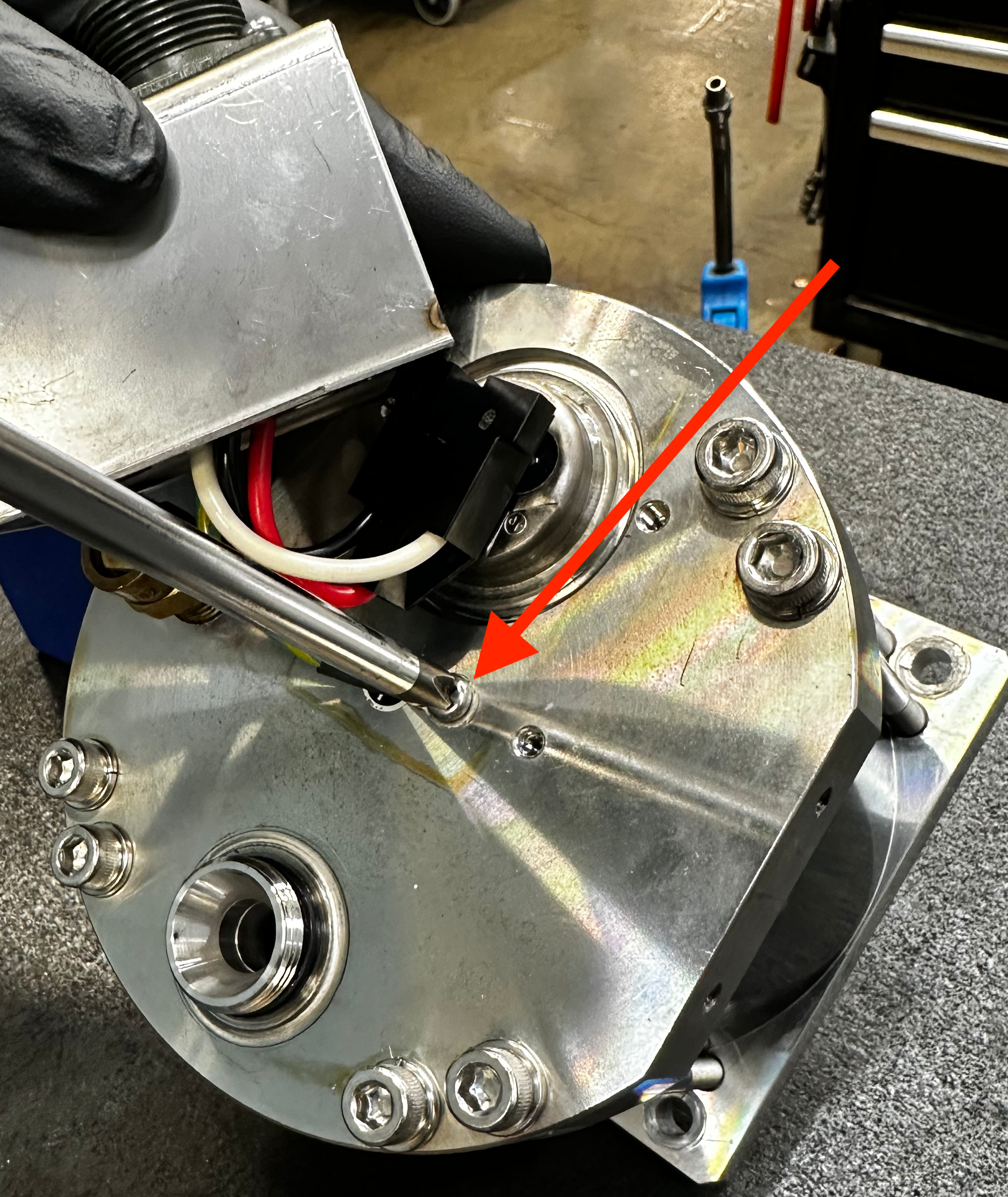
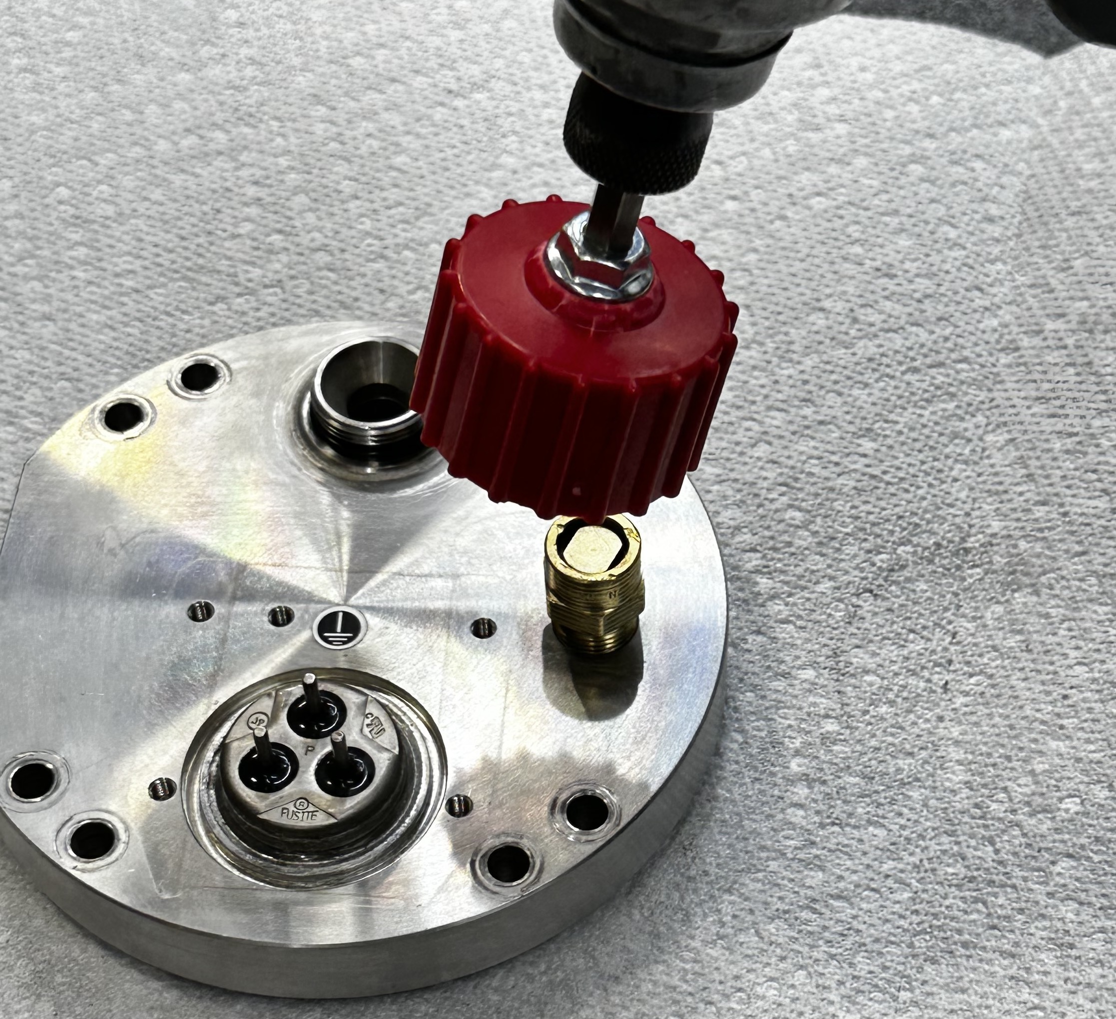
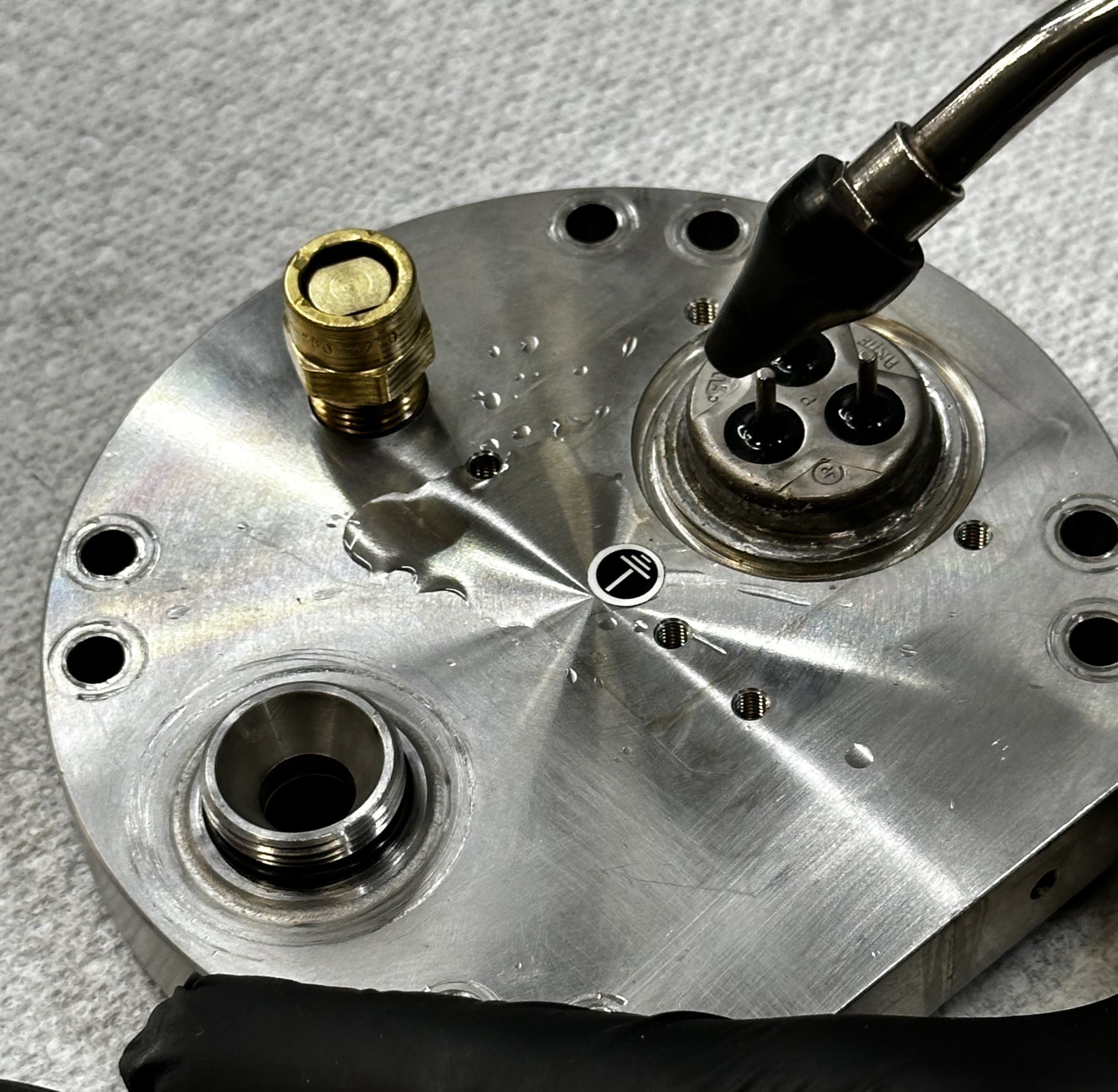
Remove the used aeroquip from the back plate using 1 ⅛” socket and recycle used aeroquip.


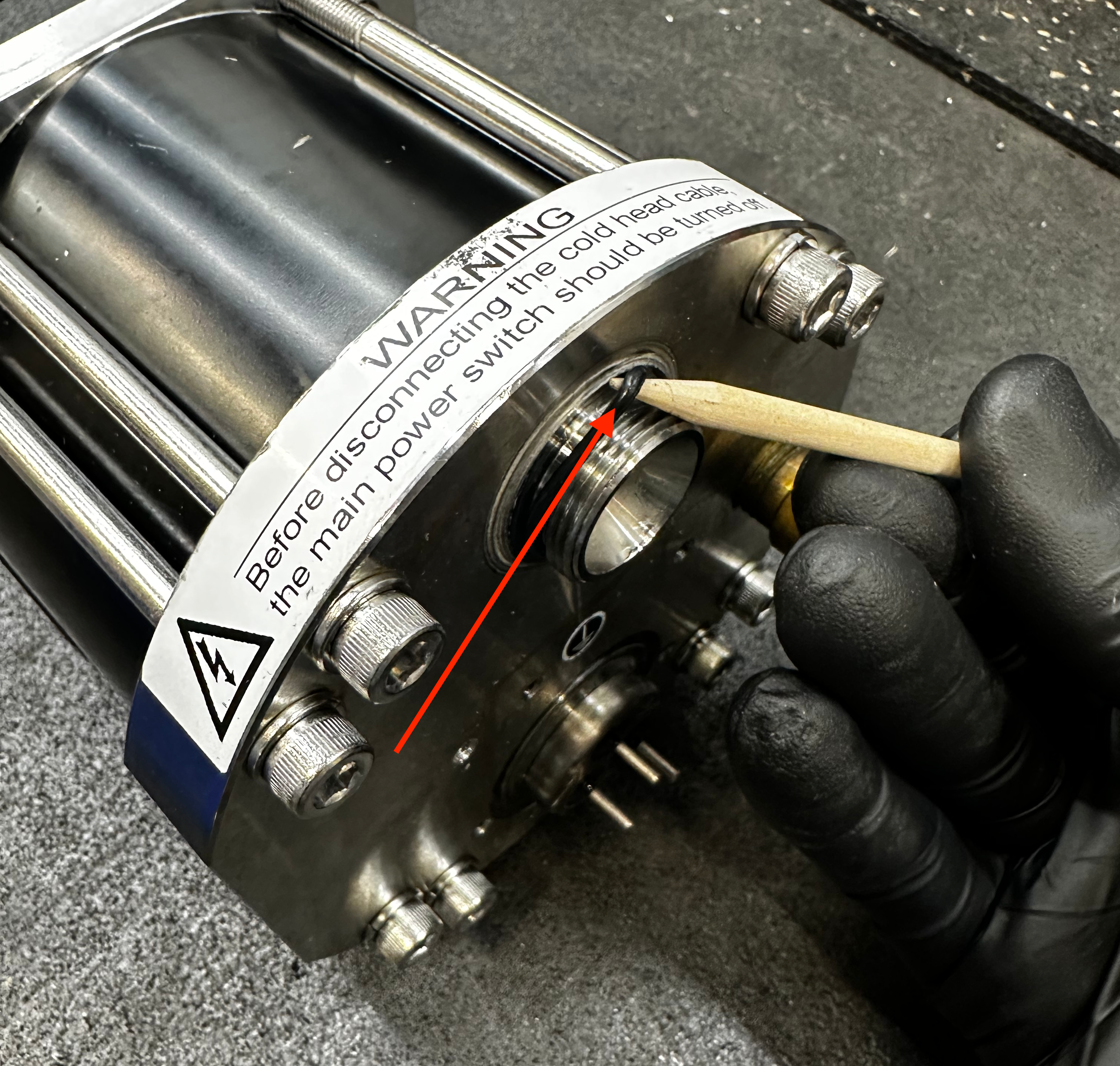
Warning
Never take a metal pick to the cold head sealing surfaces. If you must use a tool it must be a non-marring pick of wood or plastic stylus.
Remove the used -018 o-ring and discard it.
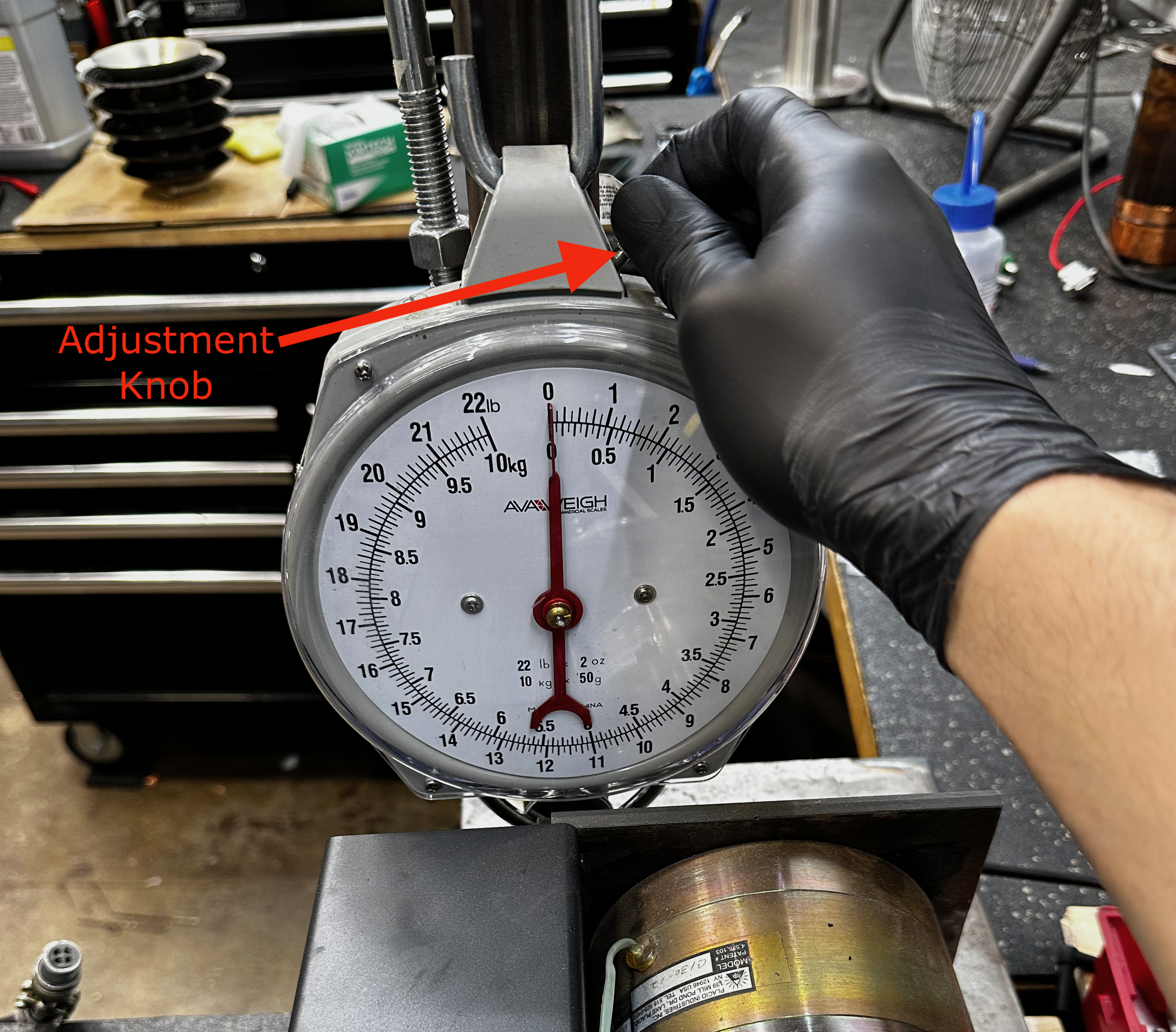
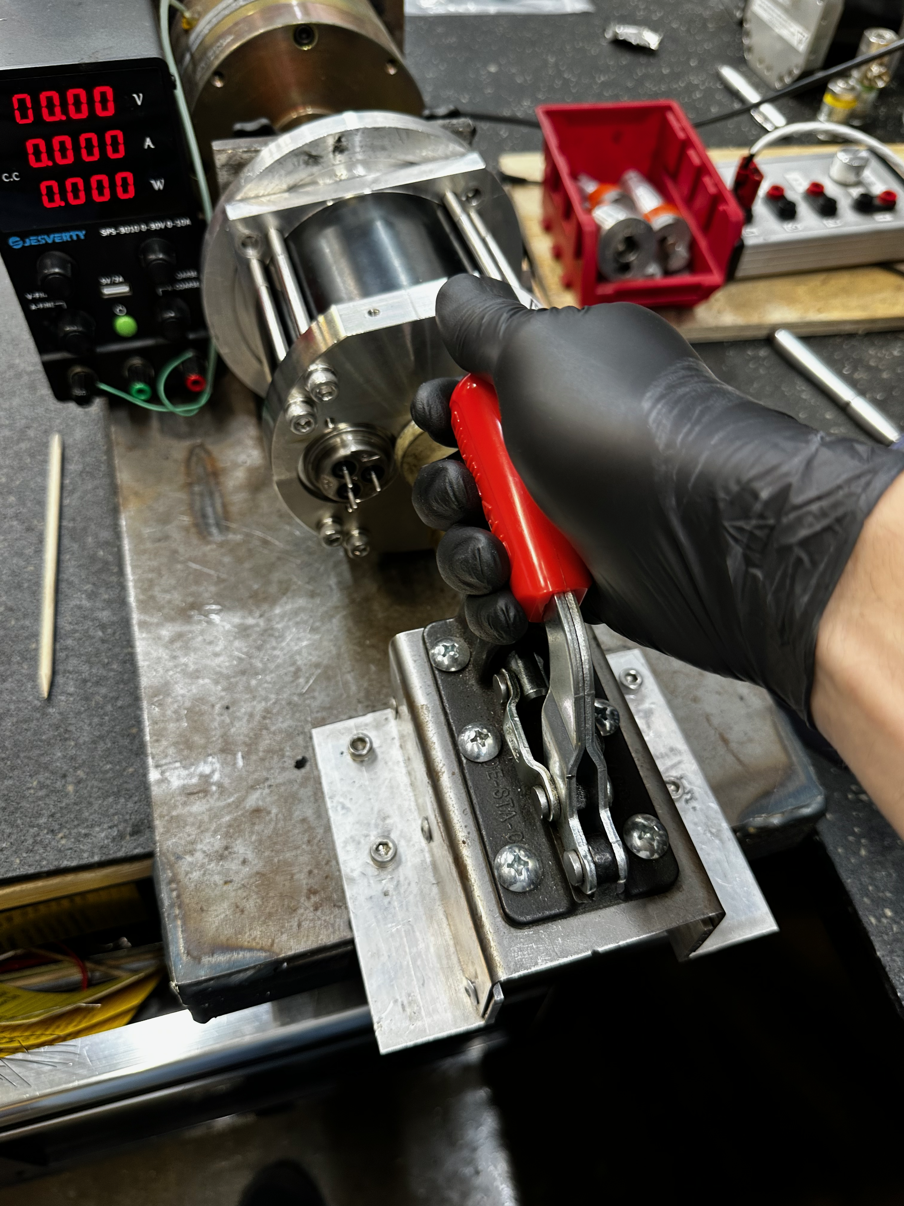
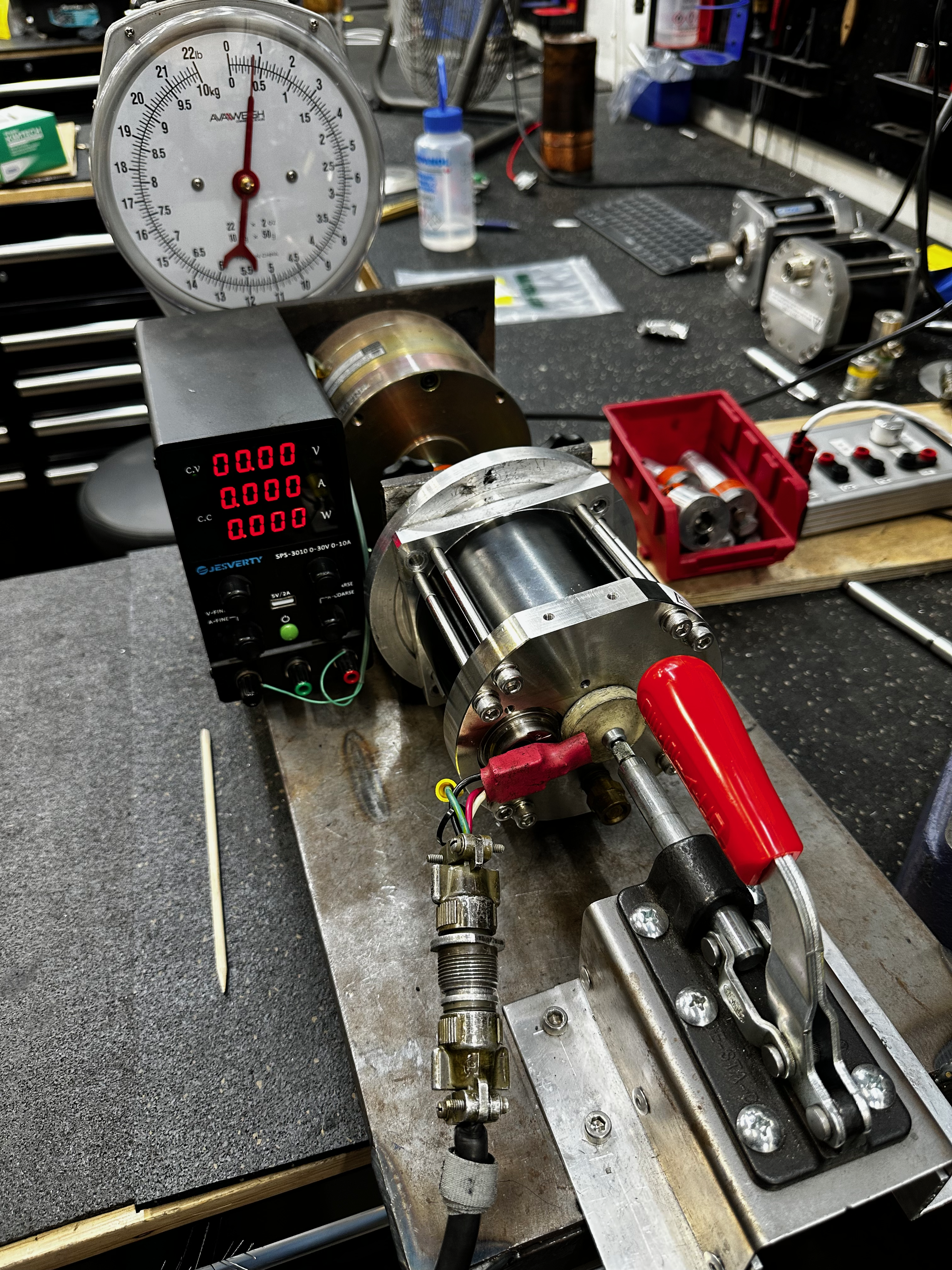
Fastening to the Torque Tester
Zero the scale using the adjustment at the top of the scale.
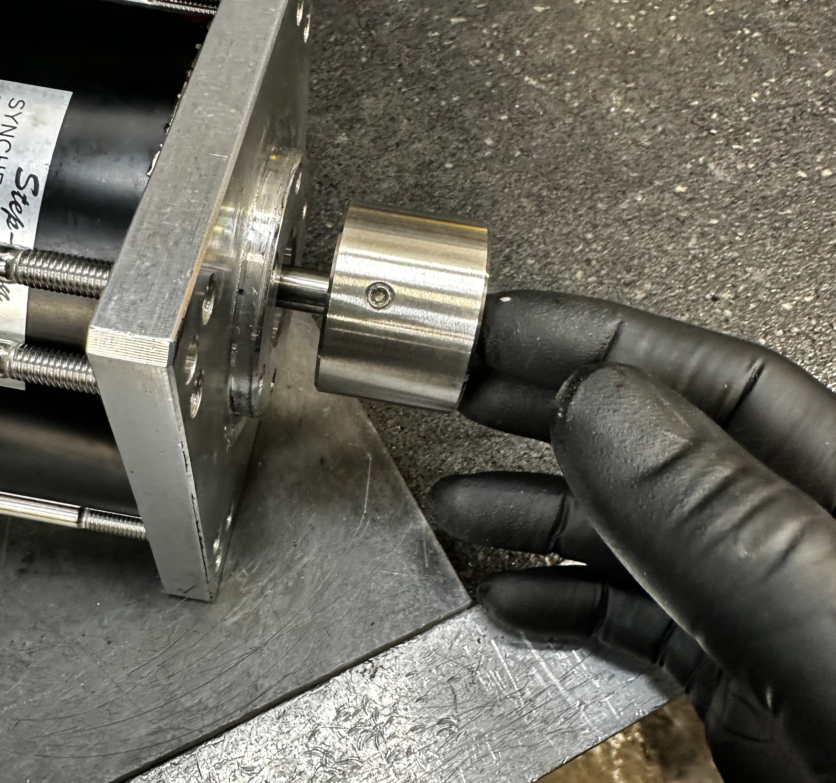
Select the crank shaft coupling labeled RDK2 and place it onto the shaft of the clutch.
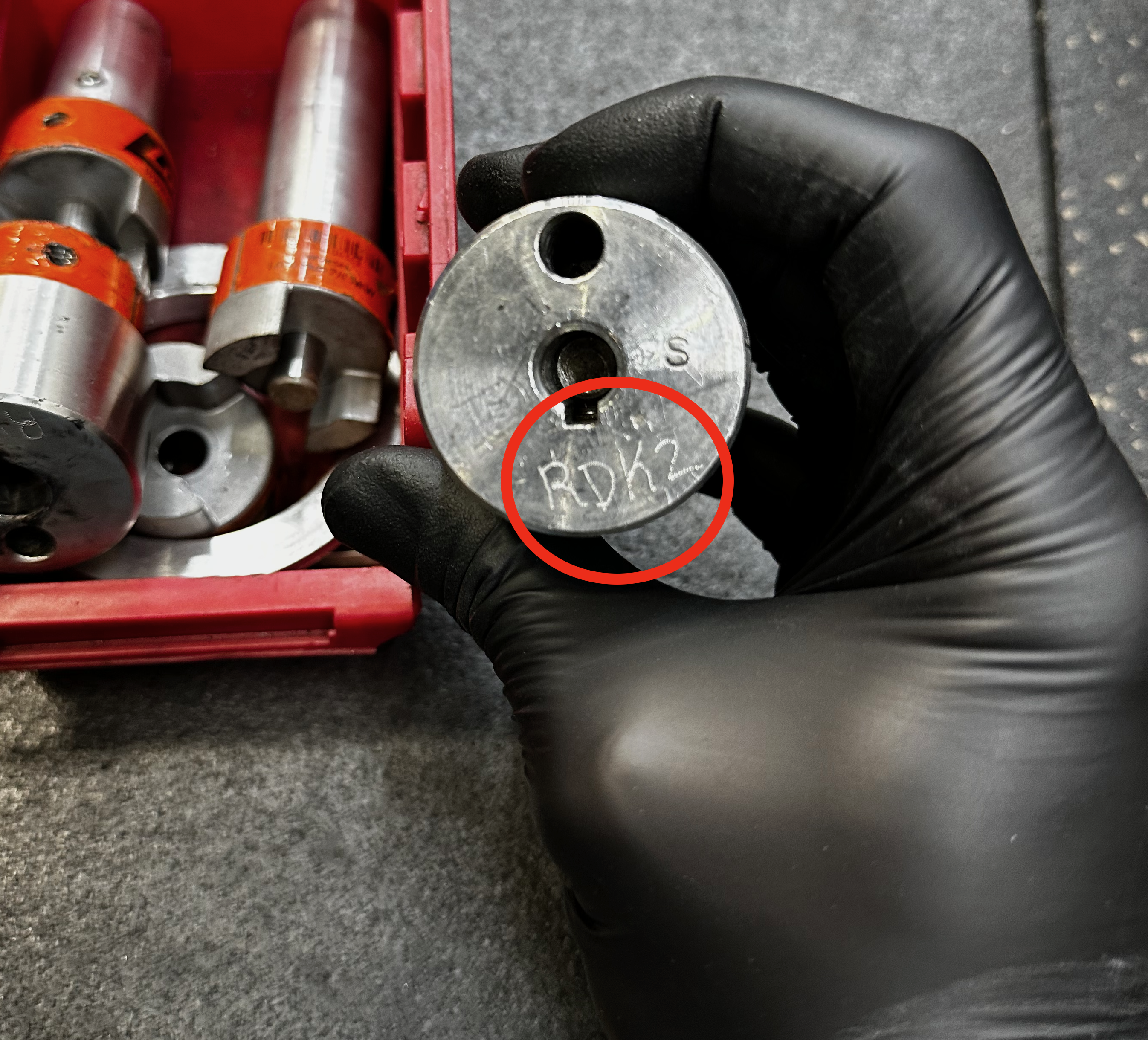
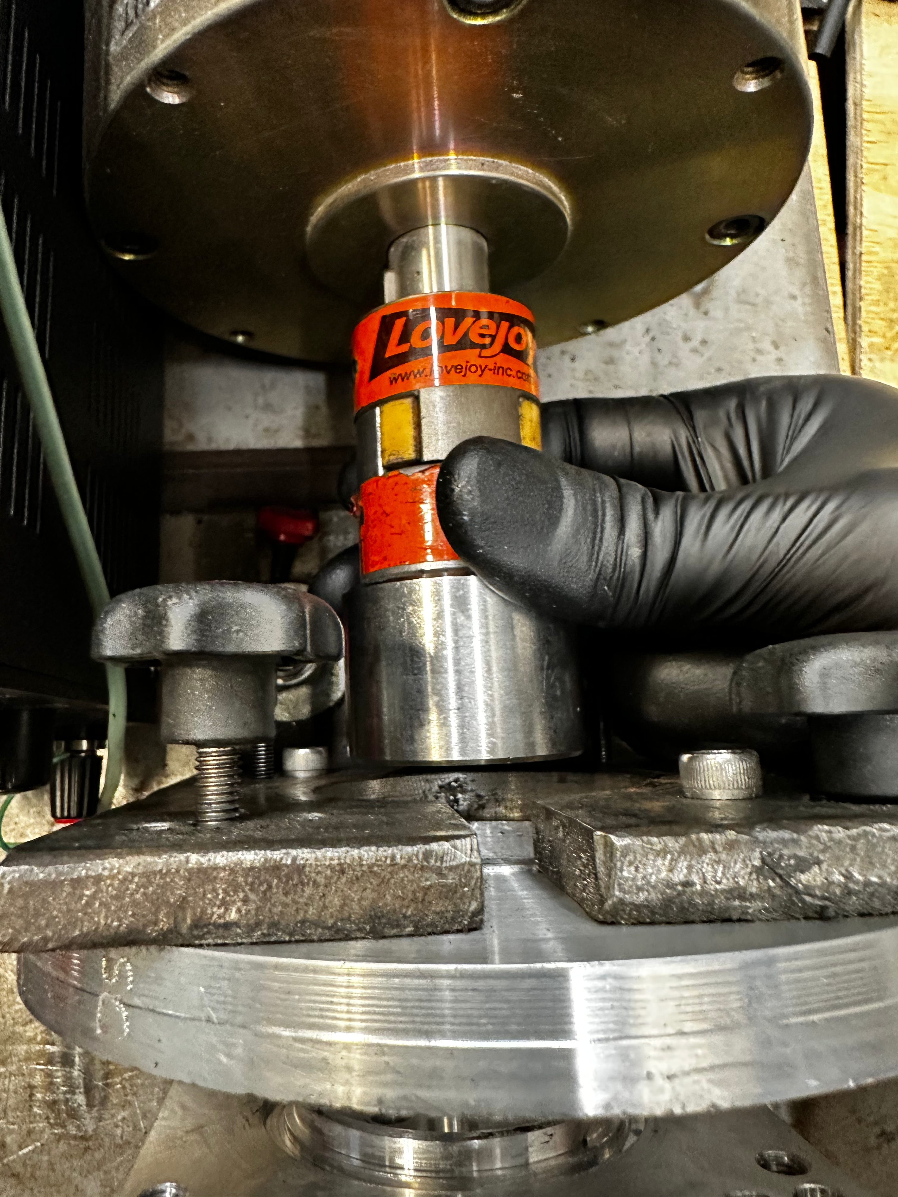
Line up the keystock on the motor shaft to match the keyway on the clutch coupling.
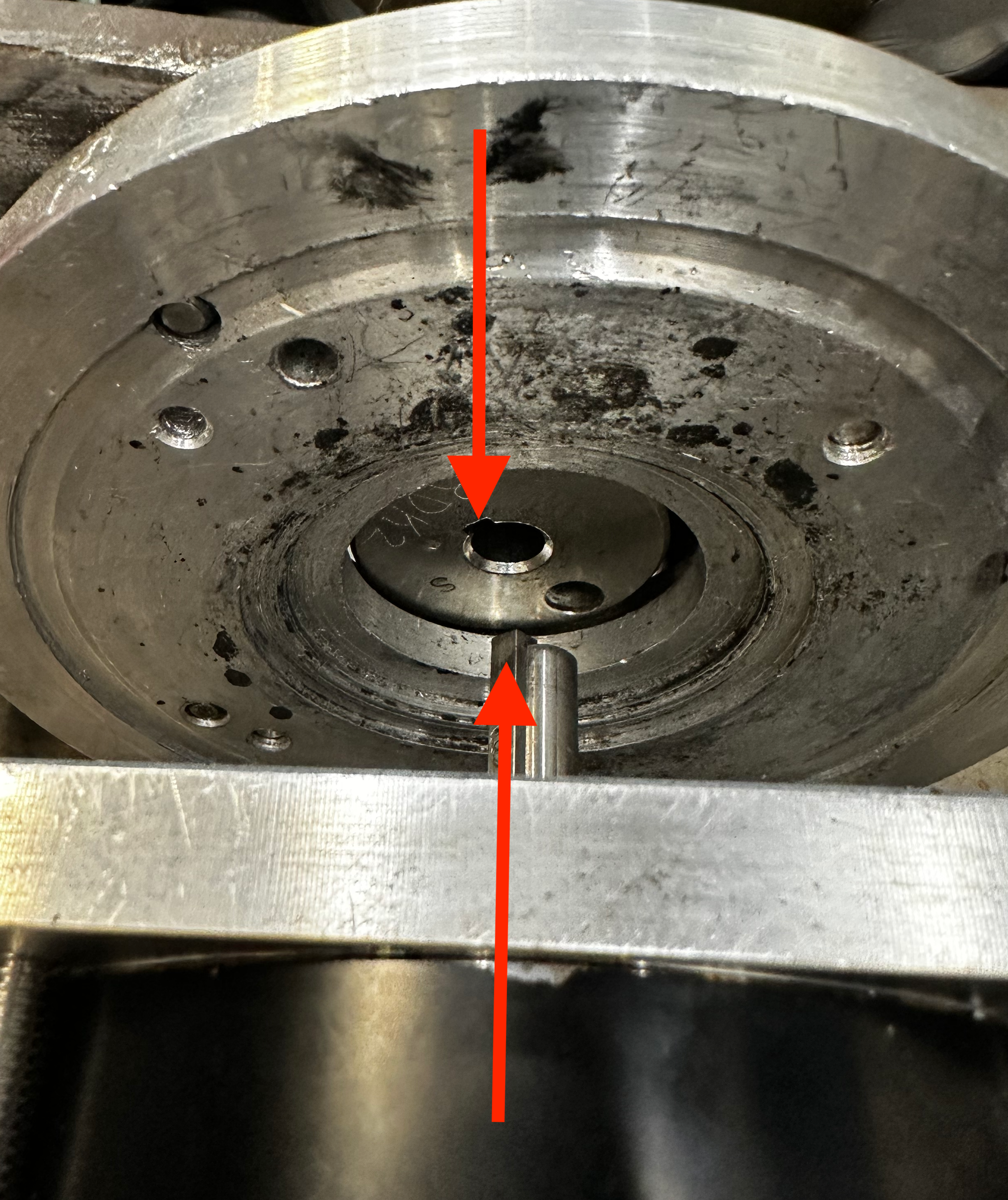
Align the alignment screw labeled RDK with the mounting hole in the motors aluminum front plate.
Note
In order to get the actuating lever to seat the motor must be oriented with the flat mounting surface on the back plate facing upwards.
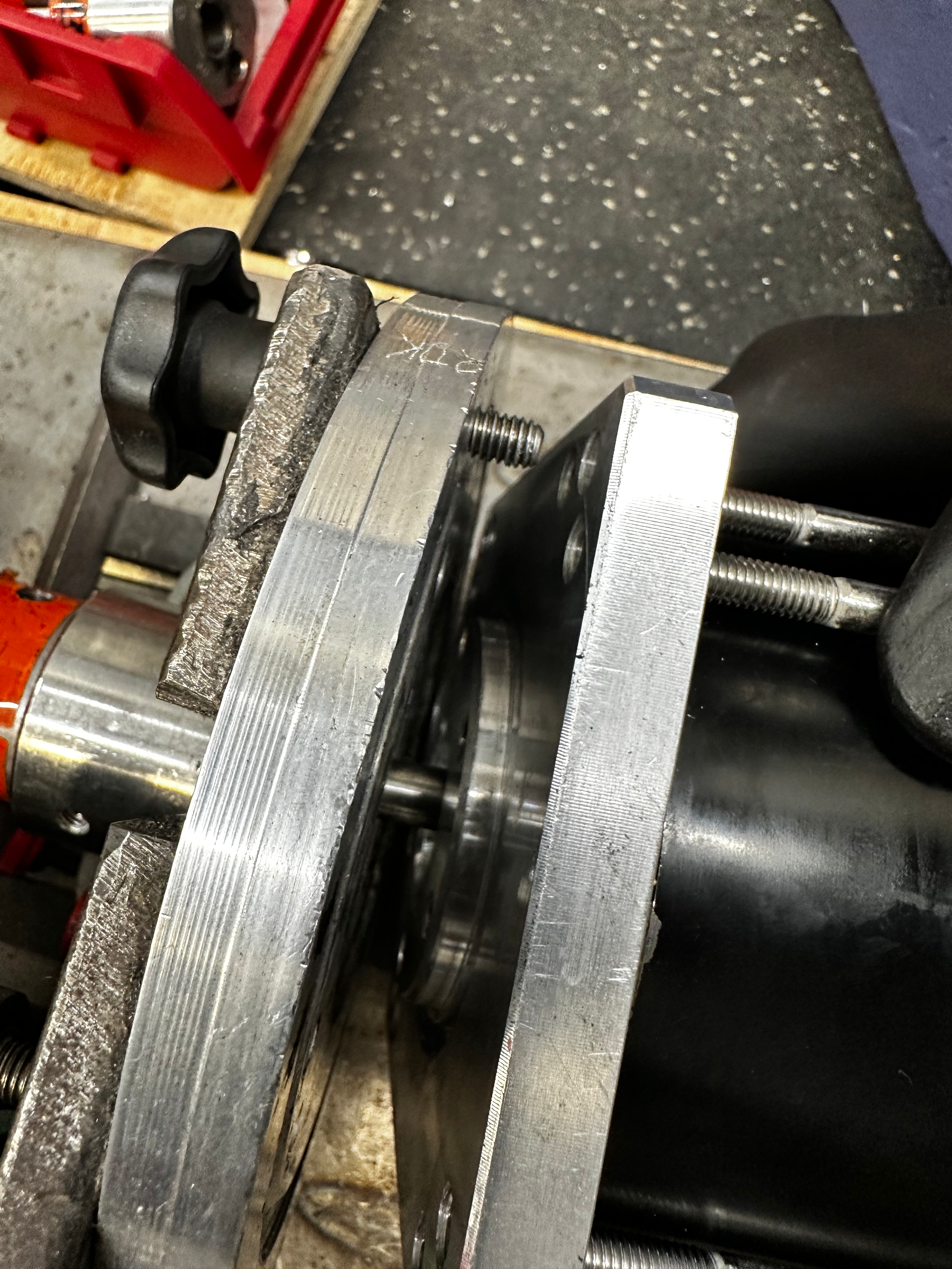
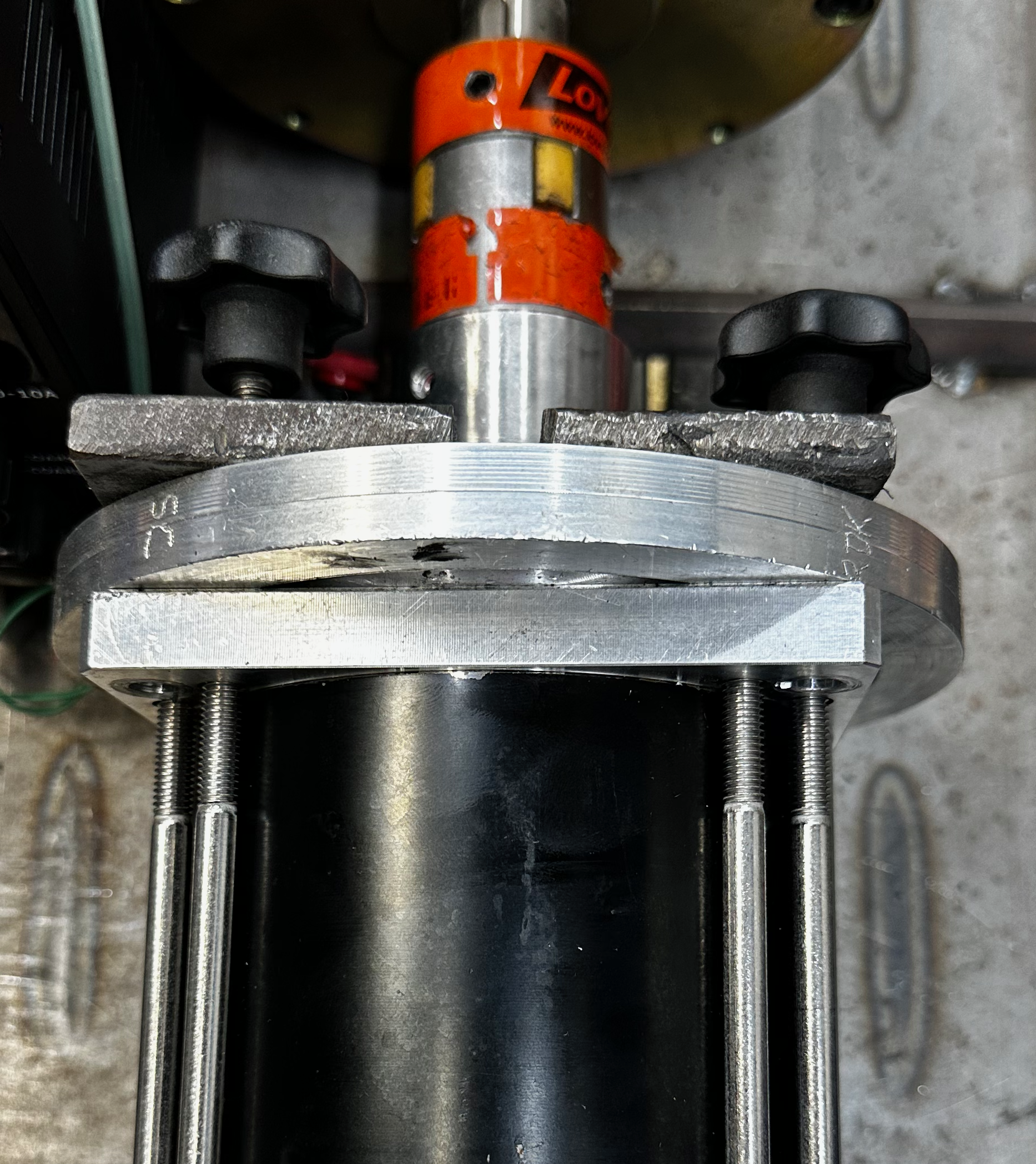
Use the red lever to push the motor flush to the torque tester.
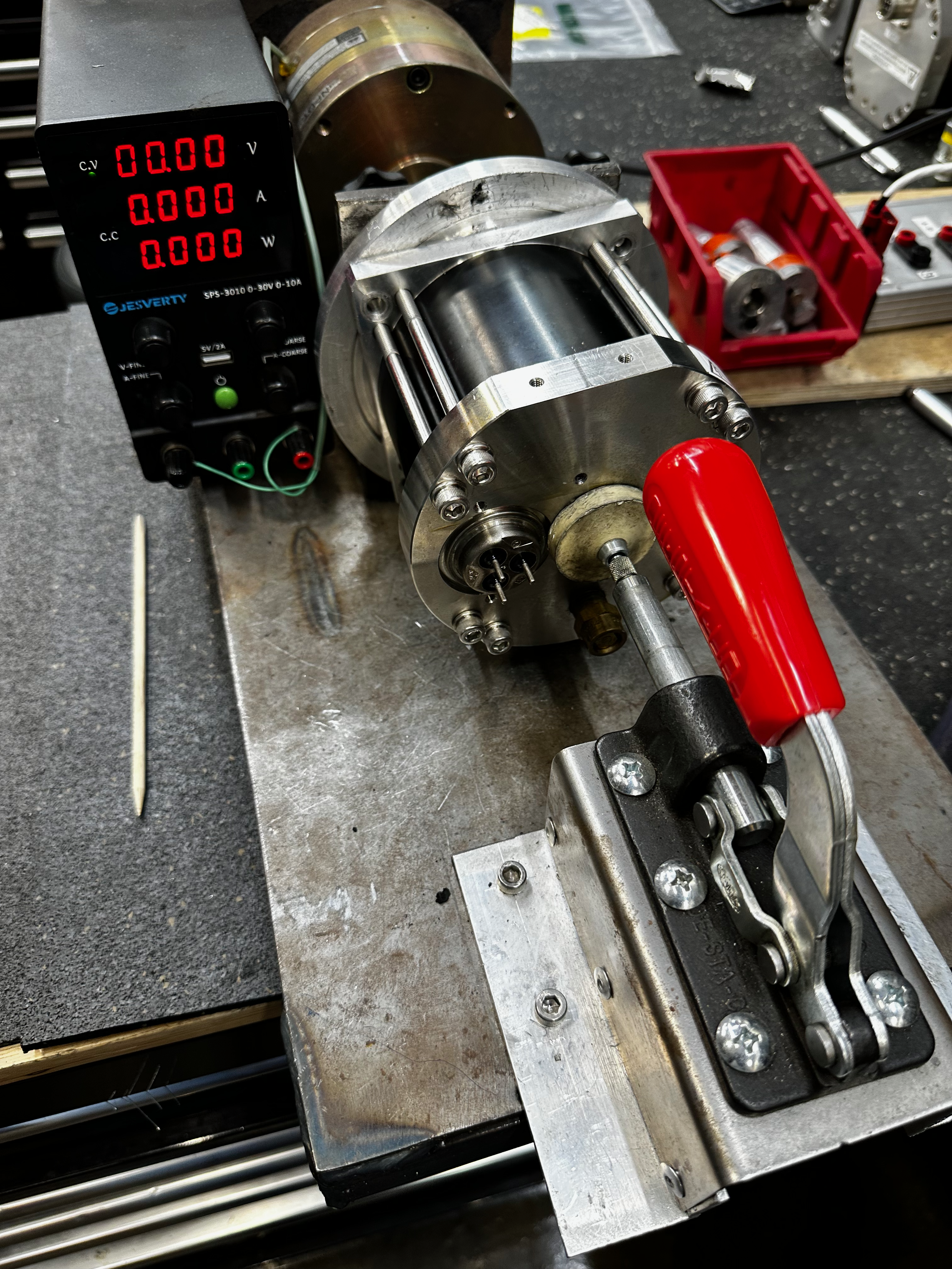
Operating the Torque Tester
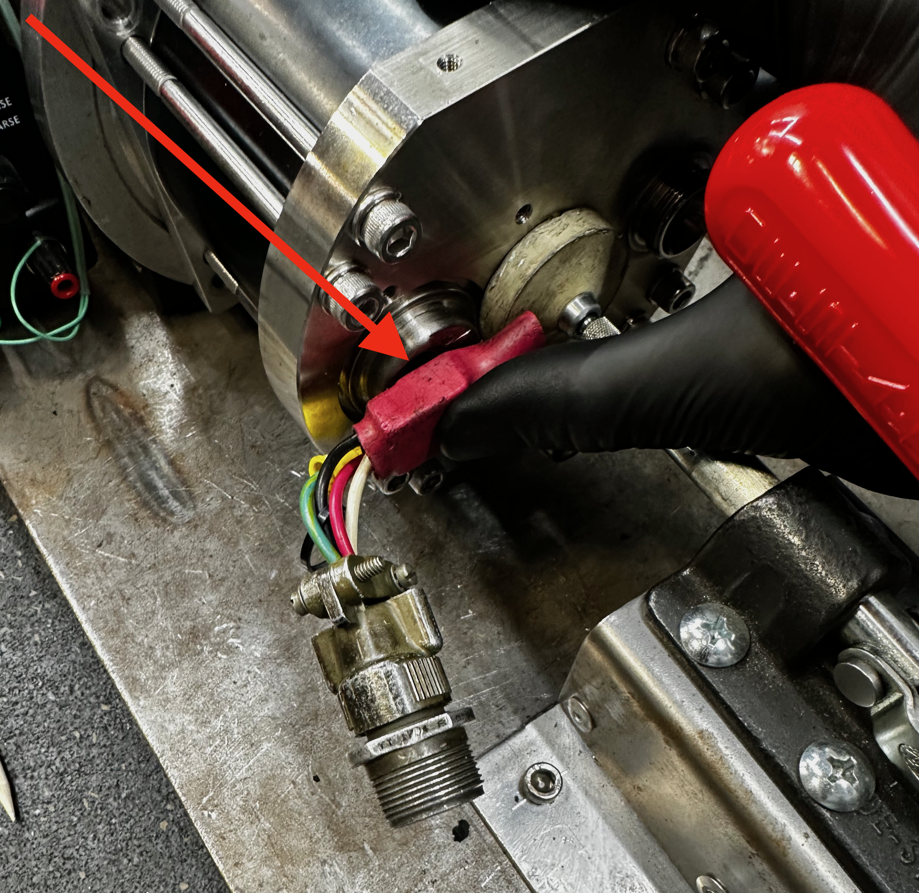
Powering the Motor
Connect the power receptacle to the motor back plate and energize.
Energizing the clutch
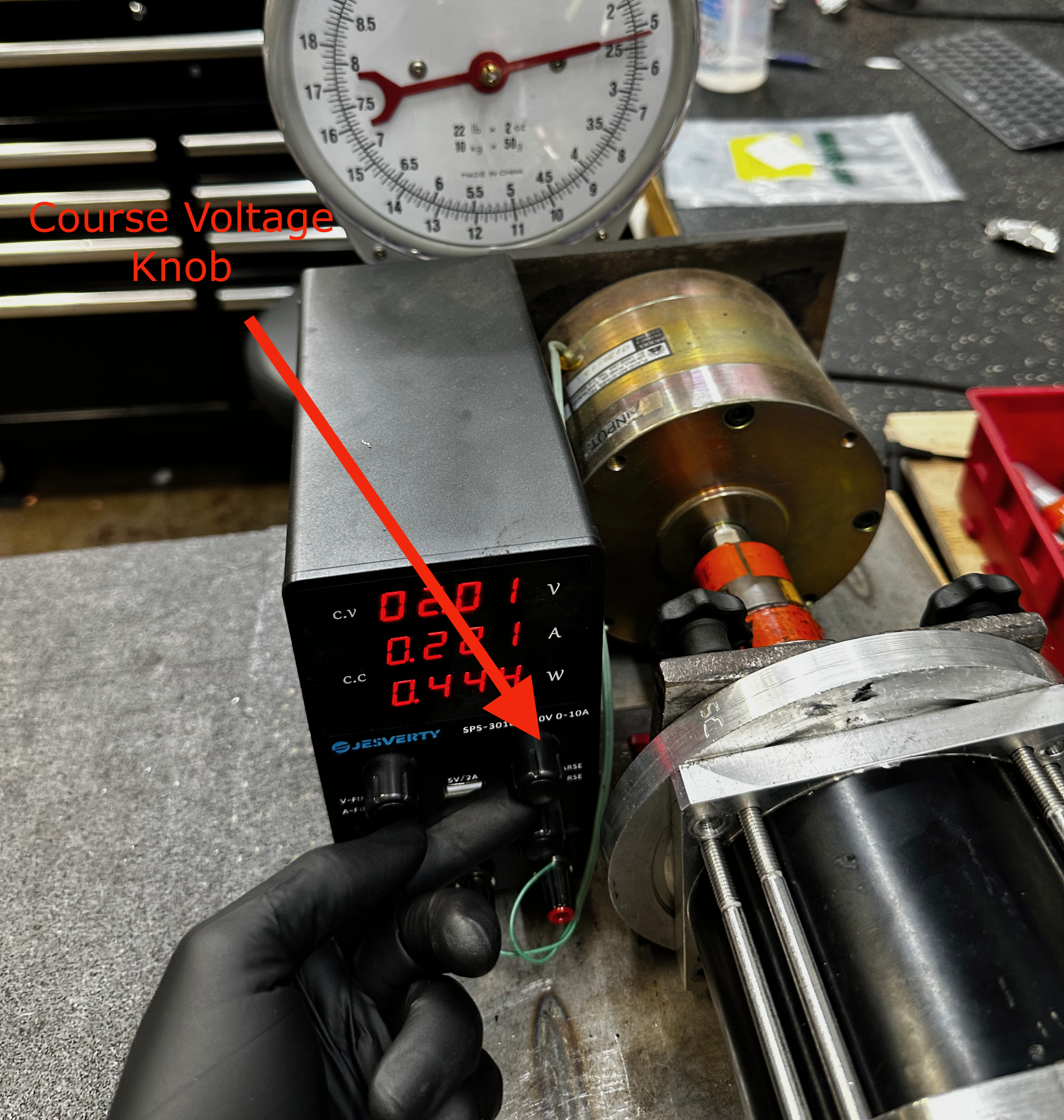
Power on the torque testers power supply.

Slowly increase the course voltage by rotating the knob clockwise.
Note
The course voltage knob is very sensitive and requires very slow movement.
Recording Torque
Increase the voltage carefully observing the needles location on the internal scale labeled kilograms.
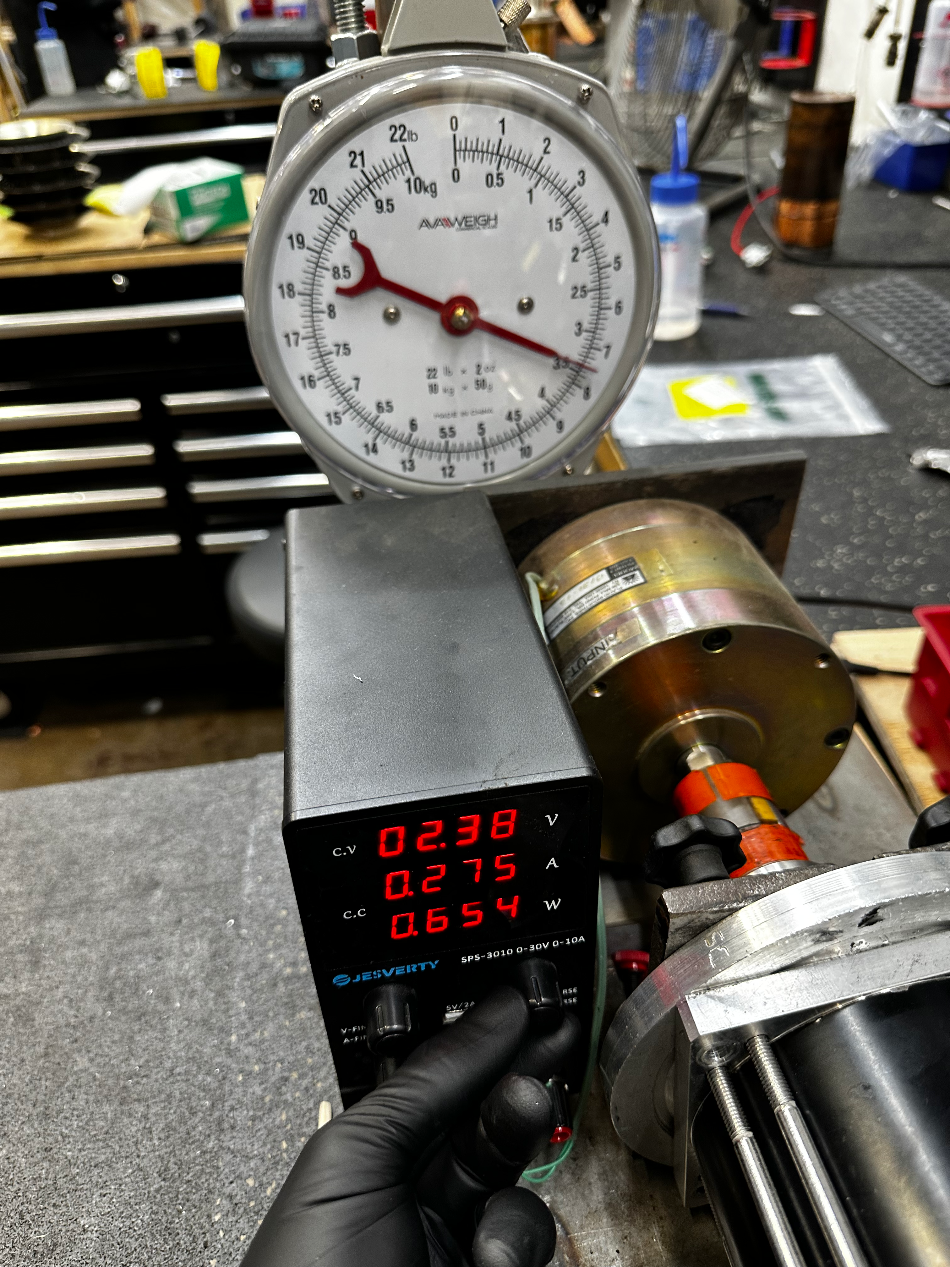
Once the motor begins to slip, take not of the highest stable location the needle arrived to prior to slipping.
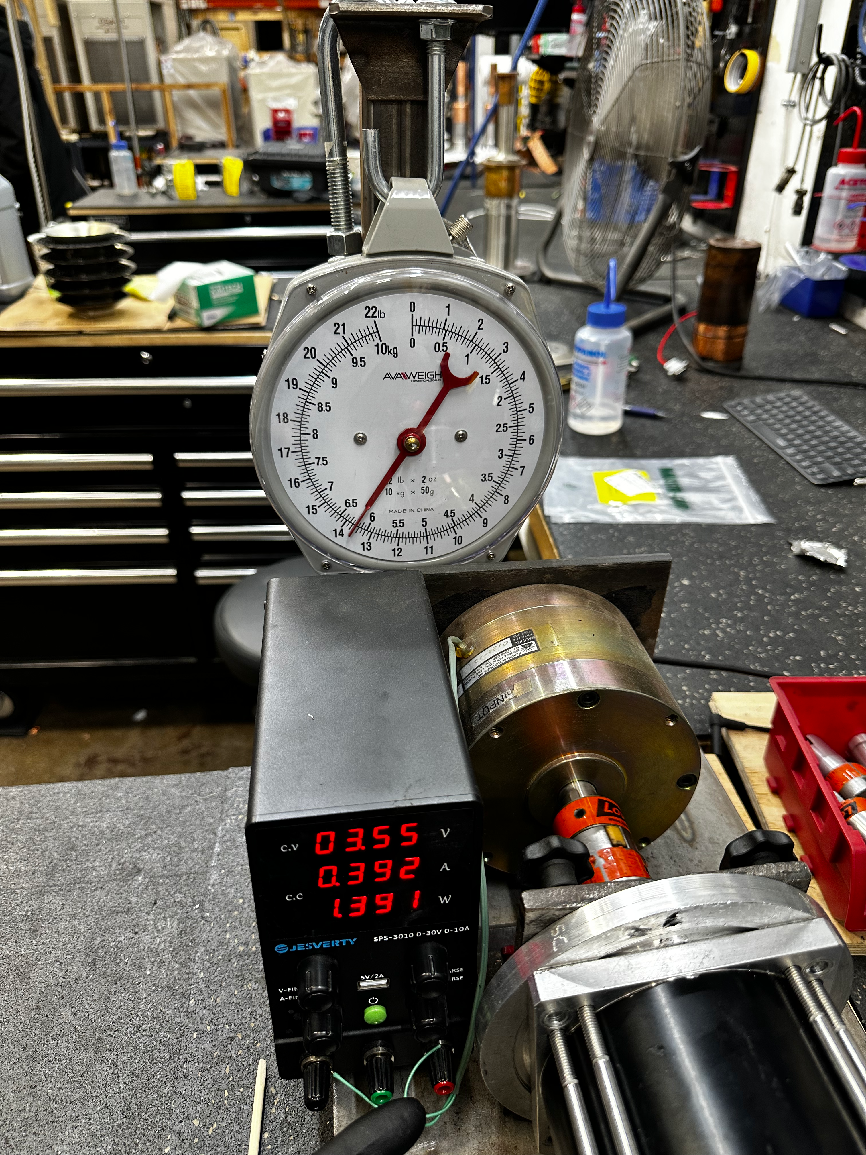

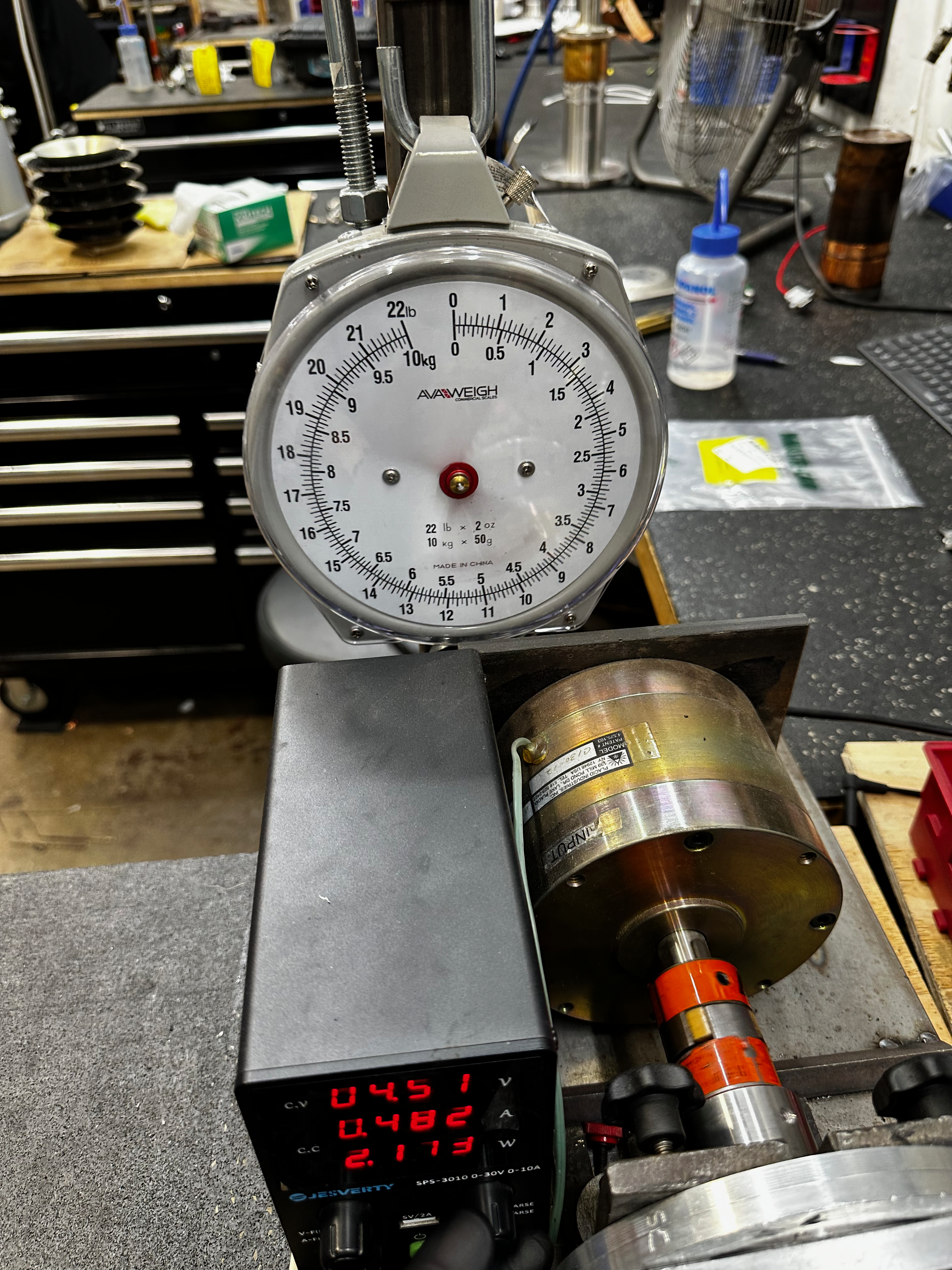
The motor torque has a pass fail threshold of 6.00kgs.
Conversion Scale
| Kilograms | in/oz |
|---|---|
| 0.1 kgs | 10 in/oz |
| 0.5 kgs | 50 in/oz |
| 1.0 kgs | 100 in/oz |
| 2.0 kgs | 200 in.oz |
| 3.0 kgs | 300 in/oz |
| 4.0 kgs | 400 in/oz |
| 5.0 kgs | 500 in/oz |
| 6.0 kgs | 600 in/oz |
Recording Vibration
Vibration is recorded subjectively.
Vibration Terms.
| Term | Fail | Pass | Ask |
|---|---|---|---|
| Smooth | X | ||
| Low VBR | X | ||
| Med BVR | X | ||
| High BVR | X | ||
| Grinding | X | ||
| Croaking | X |
Removing the Motor from the Torque Tester
Return the course voltage back to 0v by rotating the knob counter clockwise and power off the clutch power supply.
Remove the power cable from the receptacle and disconnect the receptacle from the motor.
Disengage the red handled actuator and slid the motor out of the clutch coupling.
Motor Crank Processing
Motor Shaft Reconditioning
Warning
Do not use a file. Doing so will create flat edges.
Note
Be sure to orientate the keystock to the top of the shaft.
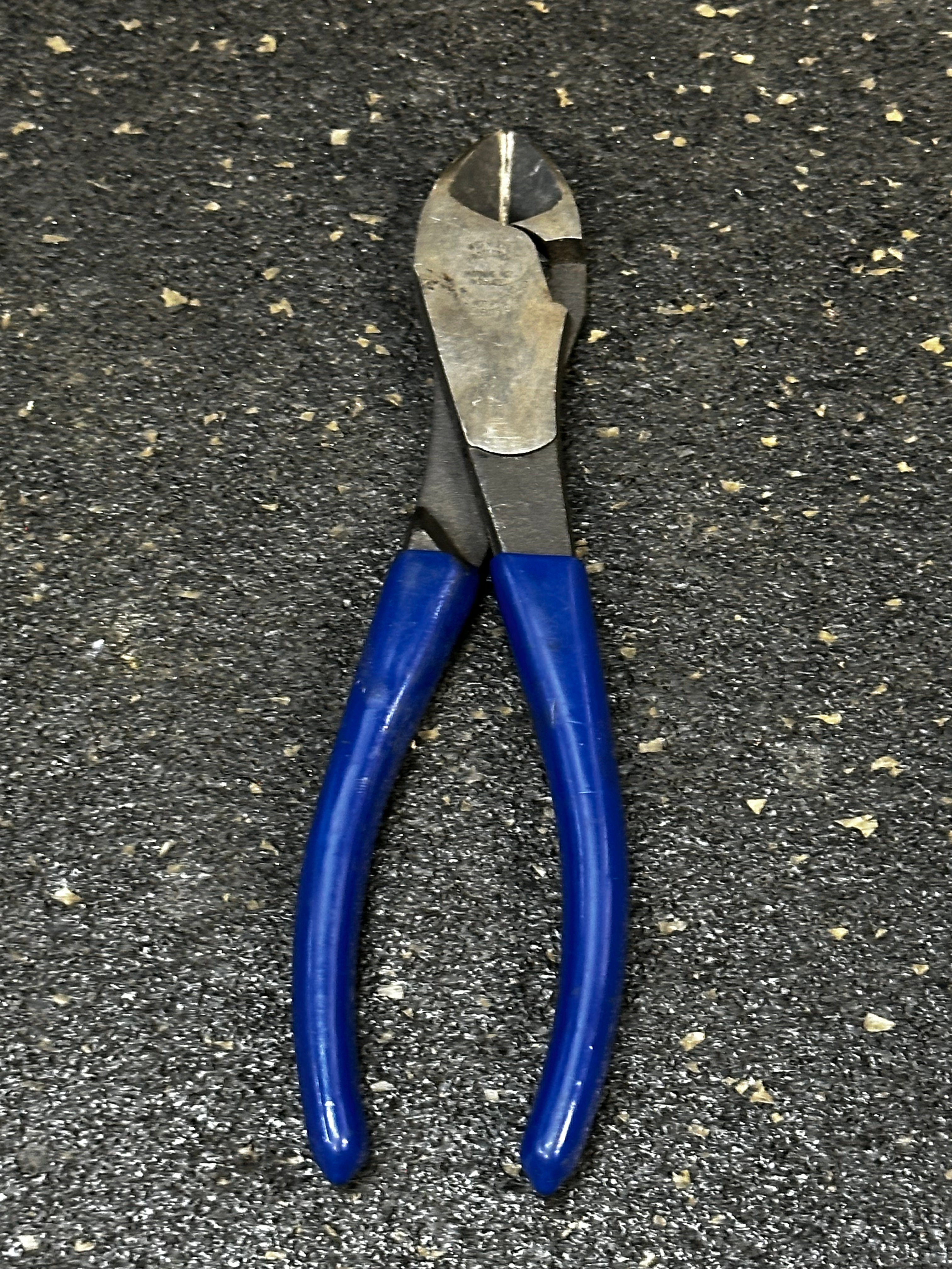
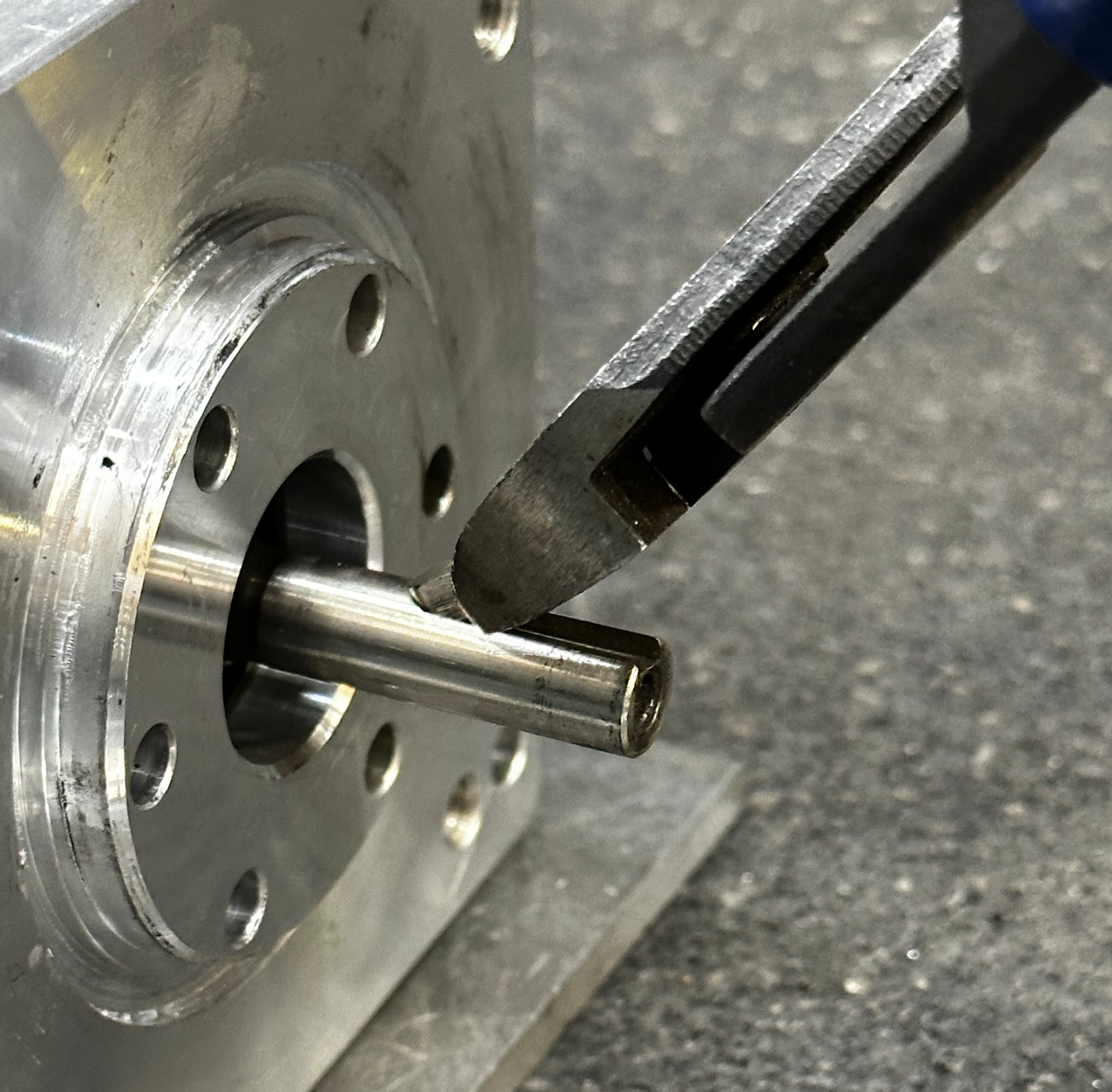
Remove the keystock with side cutters. Grip the keystock with the jaws of the side cutters as low as possible on the front of the motor shaft.
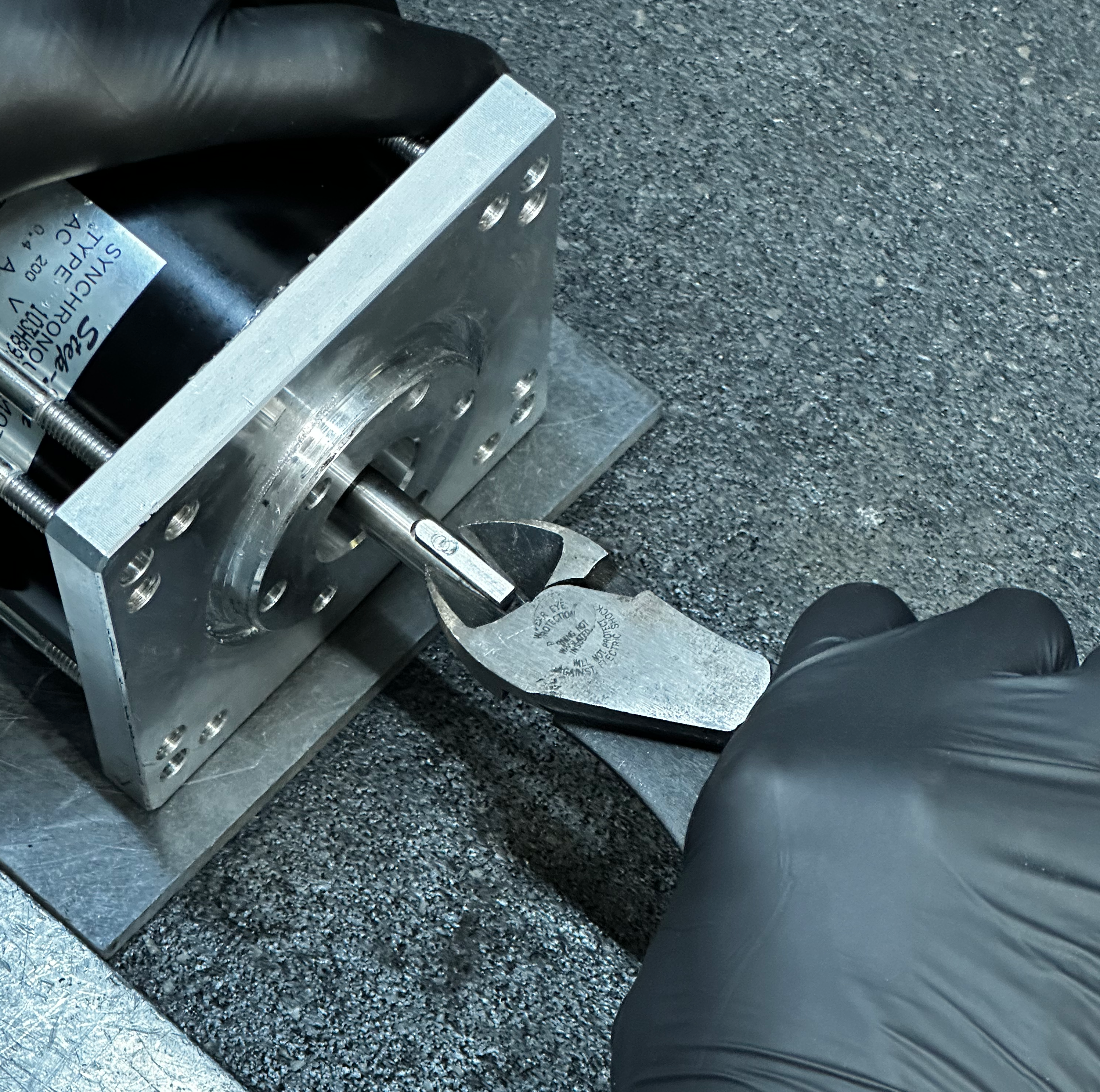
Like a lever pry upwards with the side cutters to lift the keystock out of the keyway.
Re-fit the crank onto the shaft and rotate it by hand. Be sure that the crank is slip fit and that there is no binging during rotation.
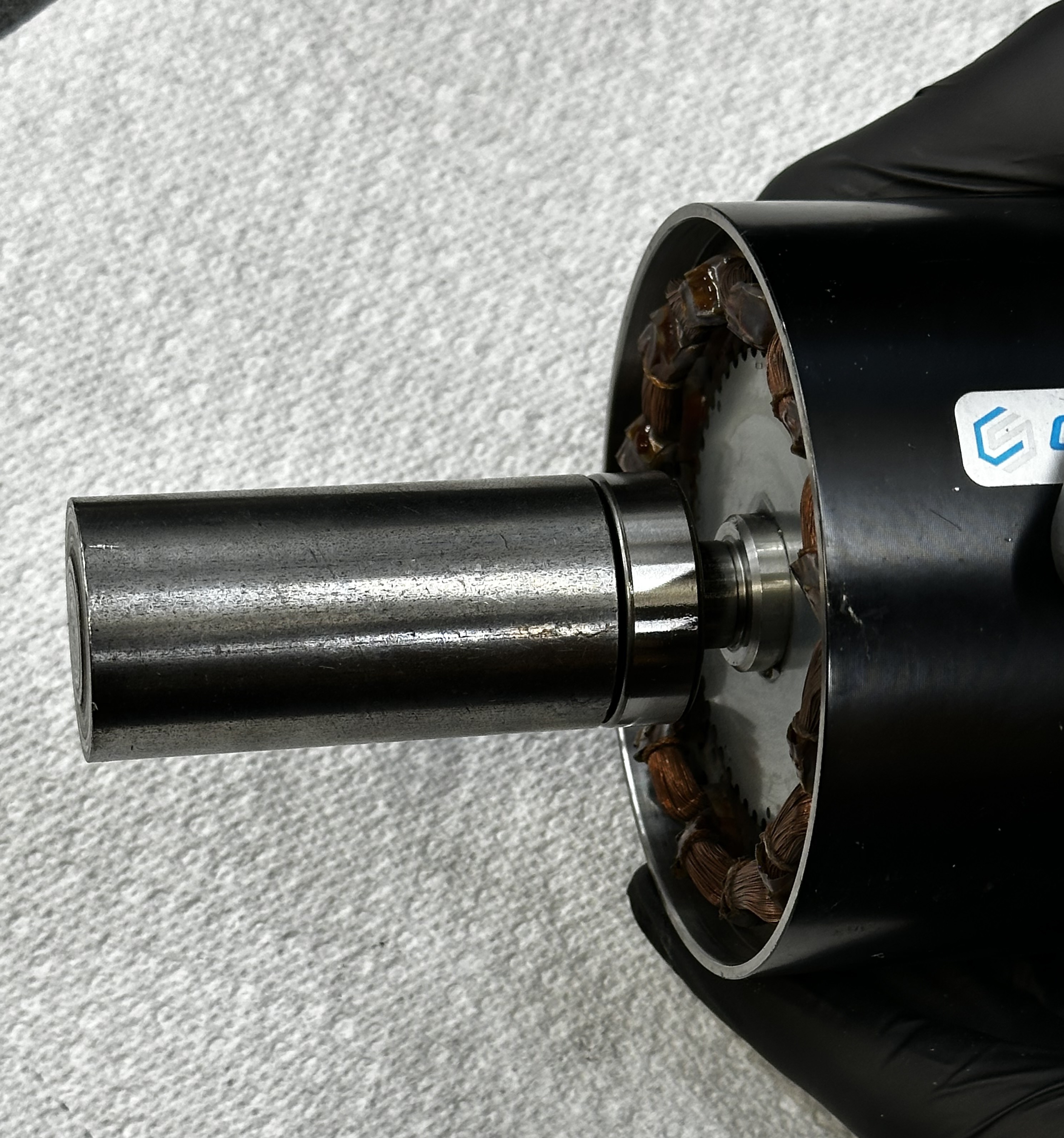
Smooth out the shaft of the rotor using the 320 grit emory cloth strips. Using a buffing motion, work all the way around the motor shaft so that all the surfaces are clear of debris and burrs.
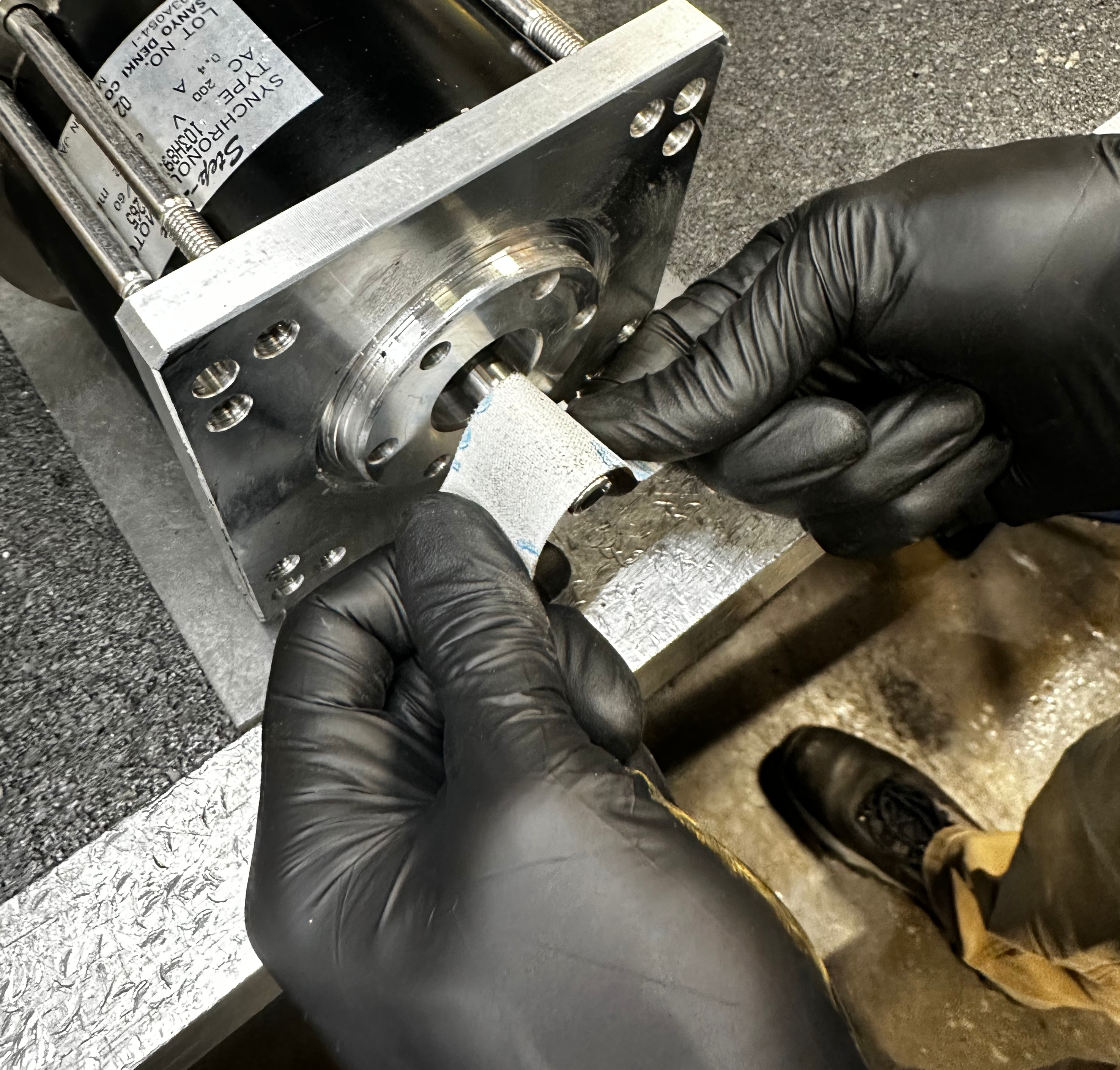
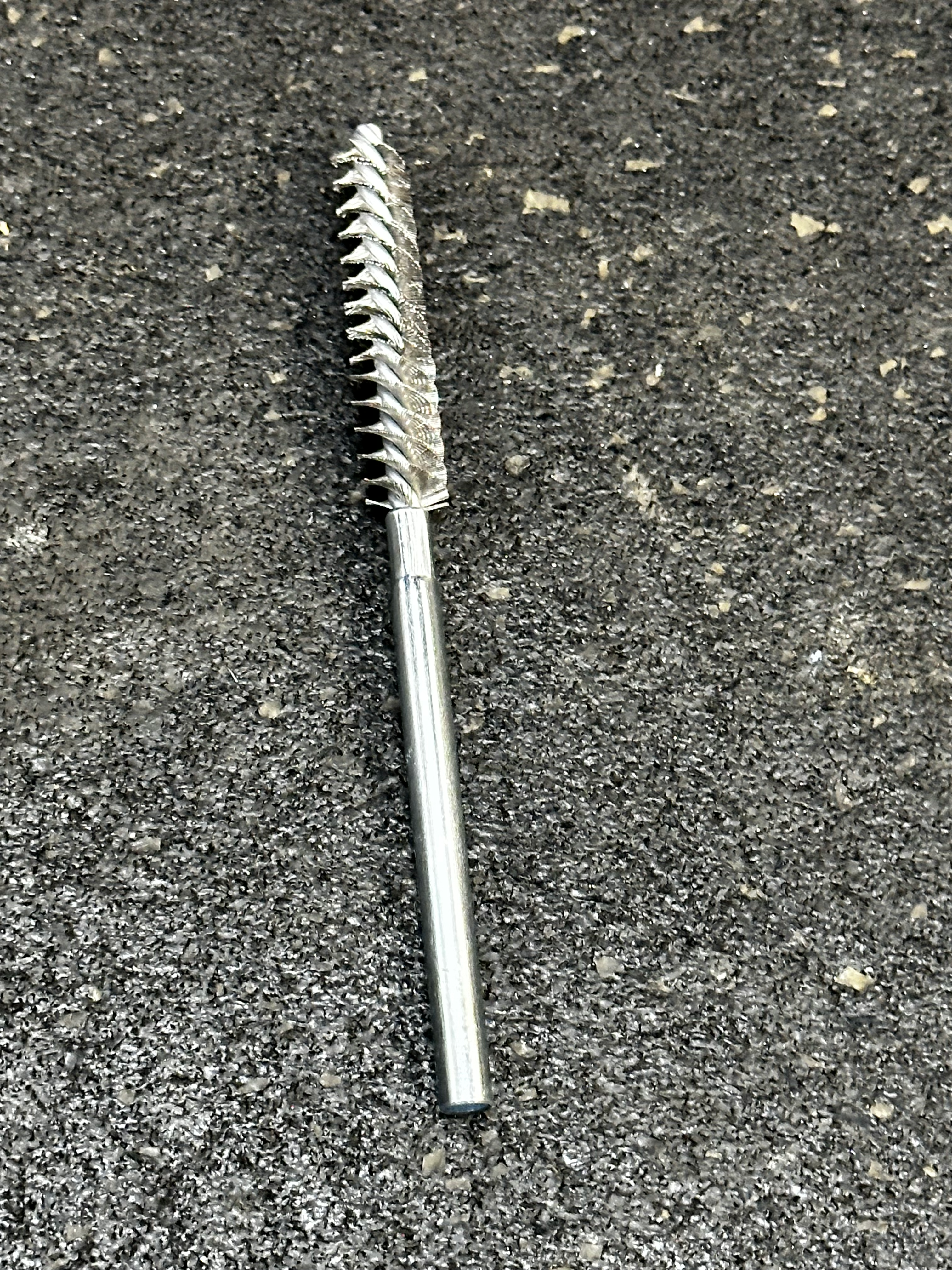
Hone the interior of the crank body with a wire brush to clear out any debris that could cause gumming.
Re-fit crank by hand and rotate to ensure slip fit. The shaft and crank body may need to be processed multiple times until it is smooth.
Replacing the Crank Pin
Pin Removal
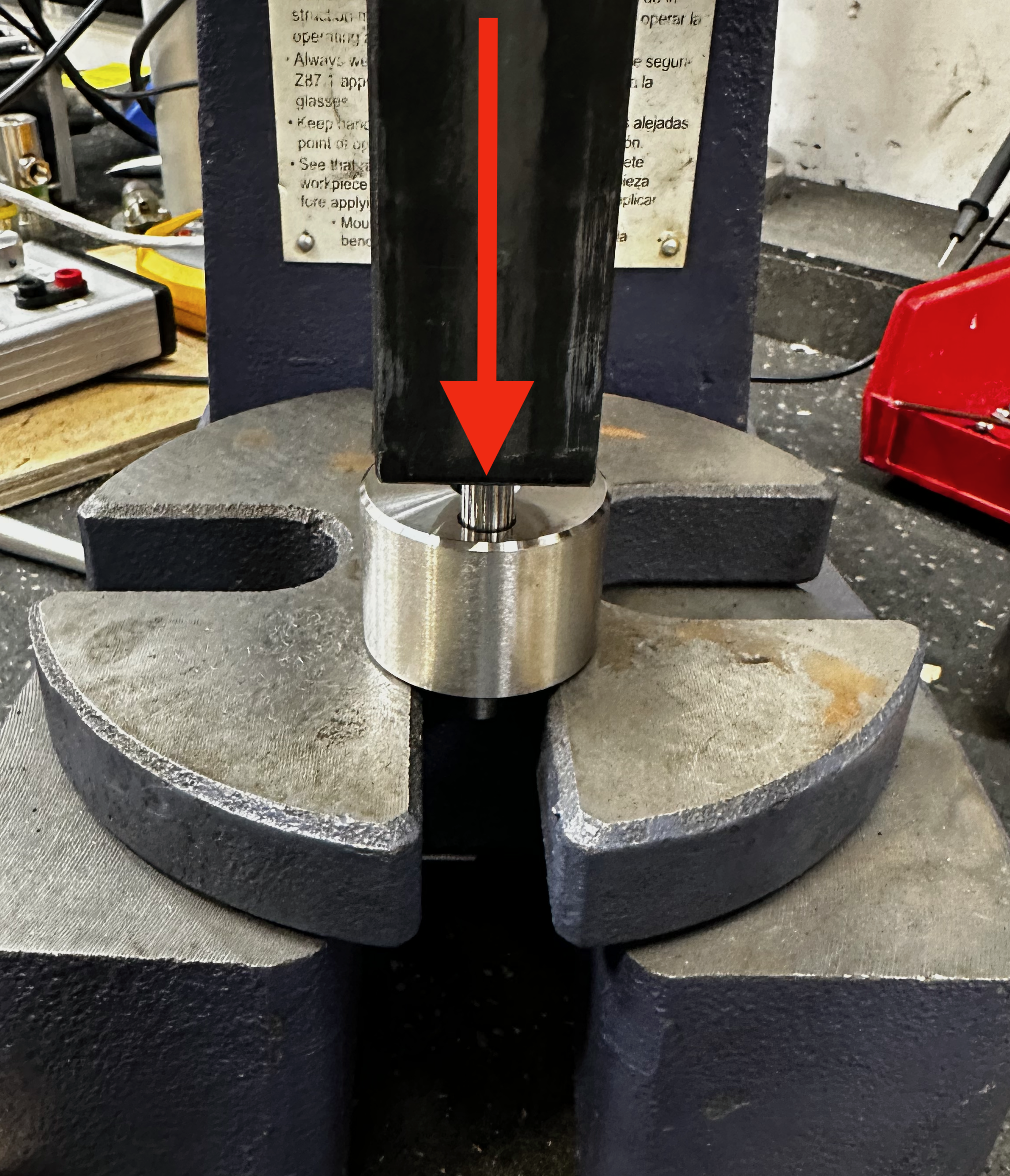
Warning
Use safety glasses when operating the hydraulic press.
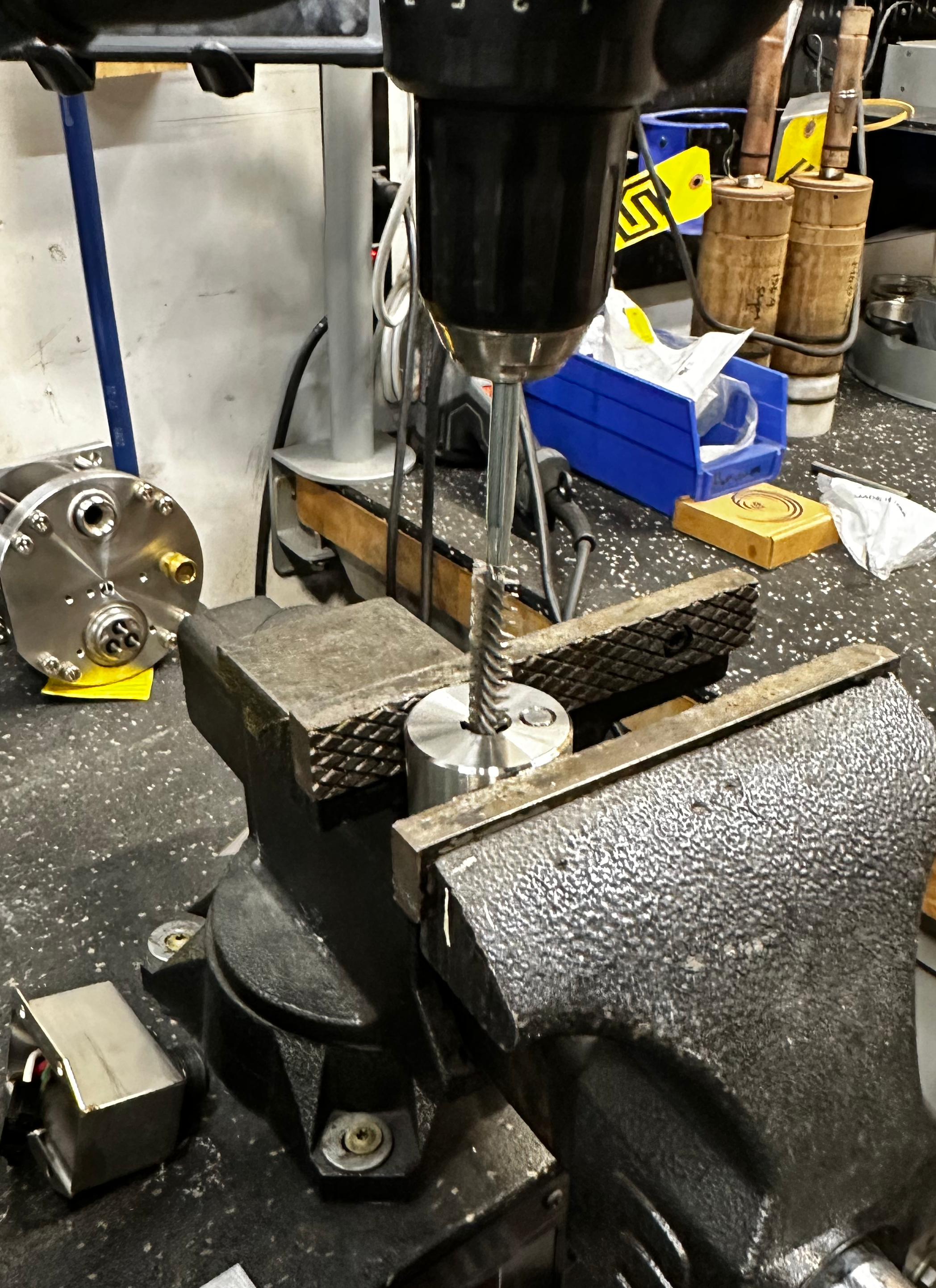
Using the hydraulic H frame press, center the crank pin under the ram of the press.
Press out the pin and recycle it.
Pin Installation
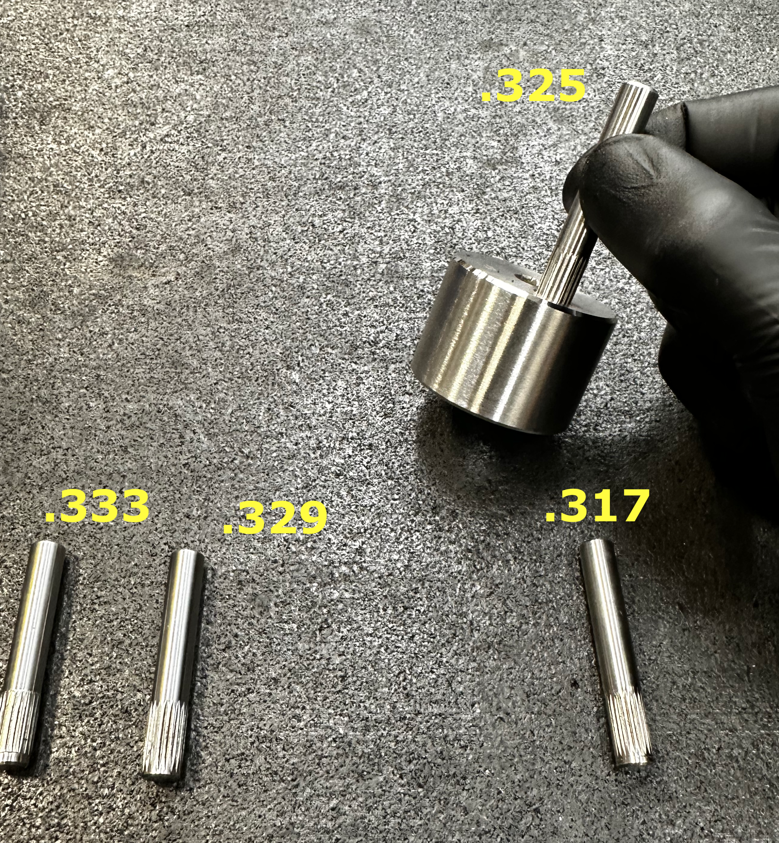
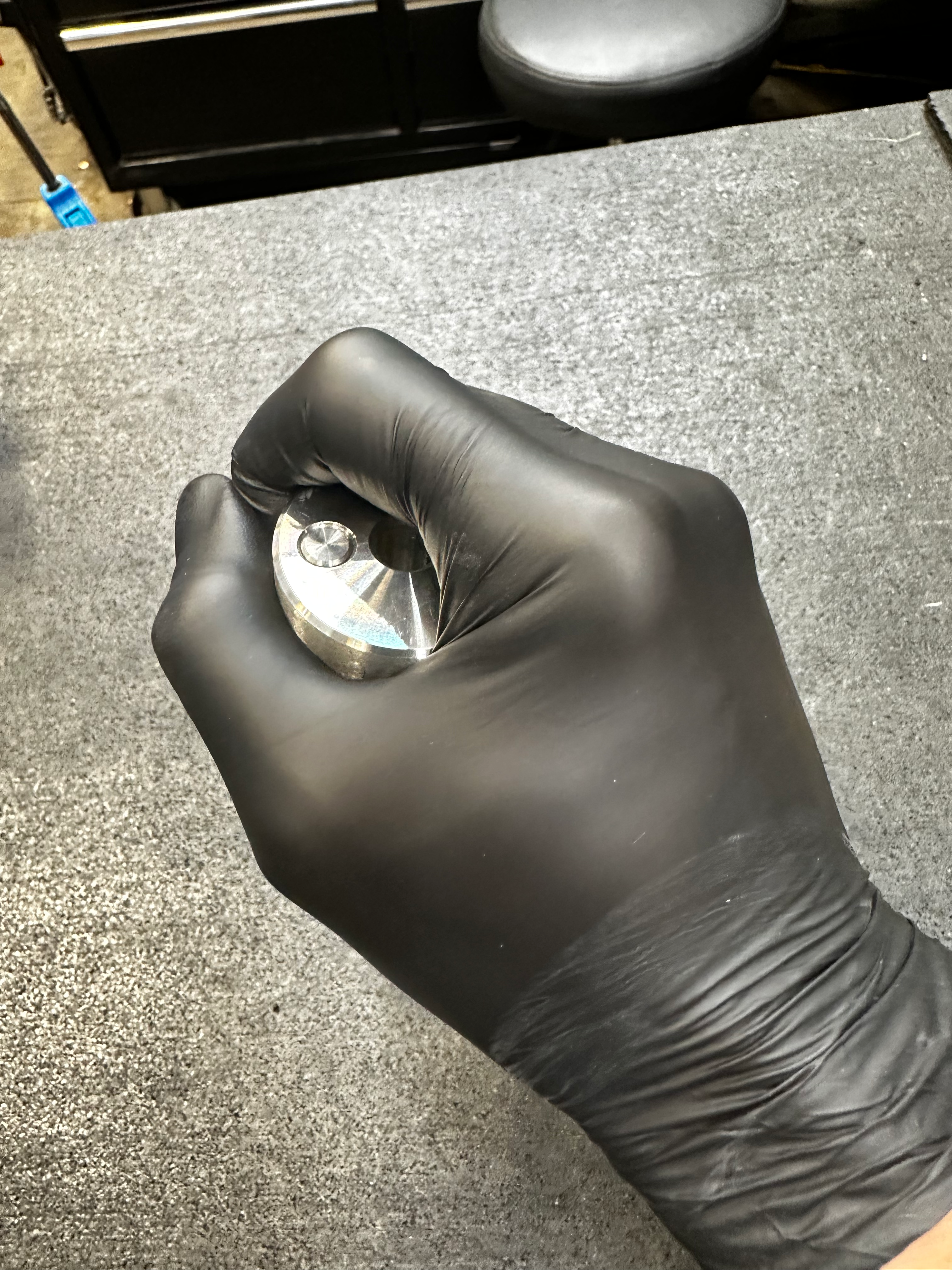
Select replacement crank pin with least amount of knurling (.317) and test fit by hand.
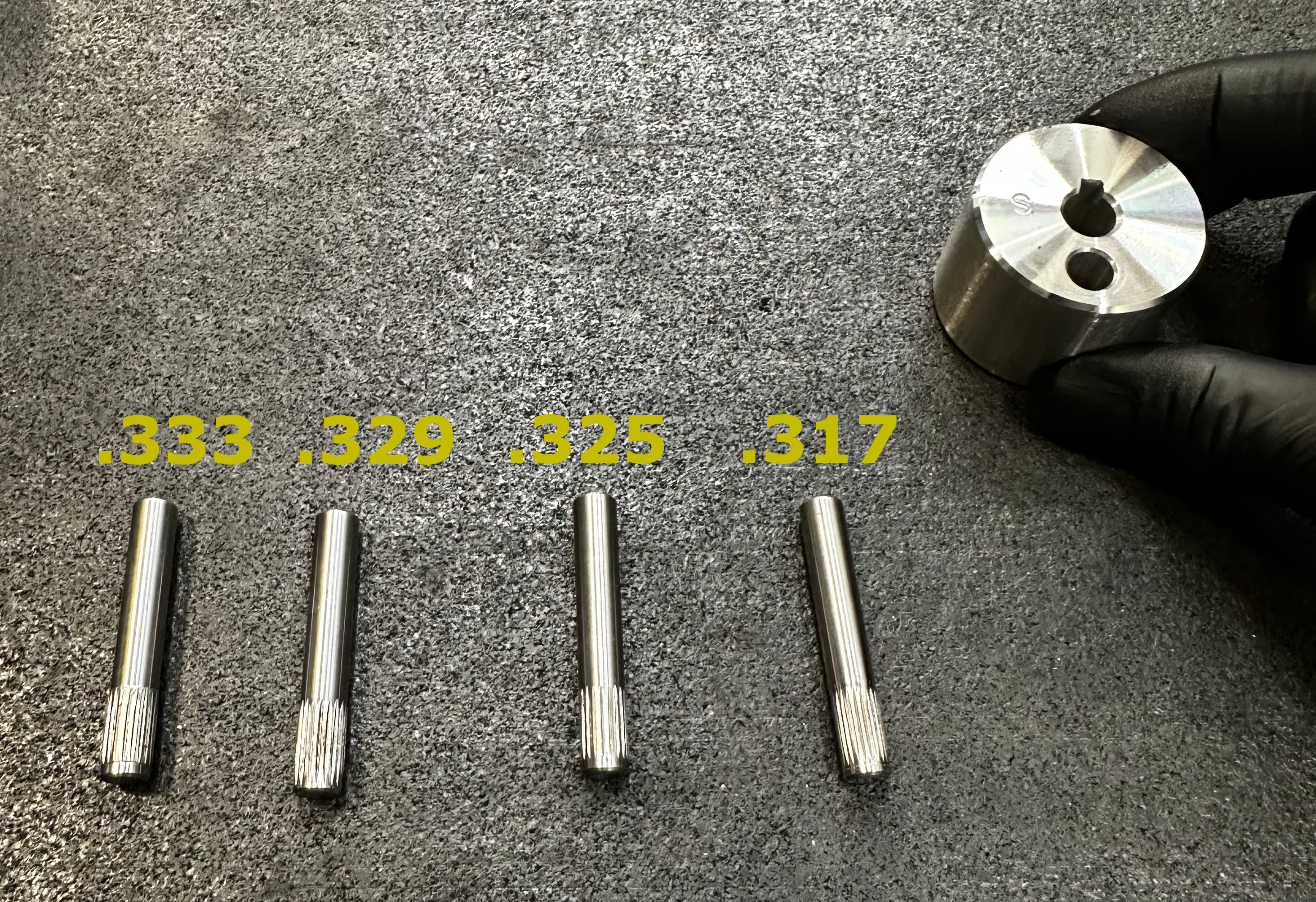
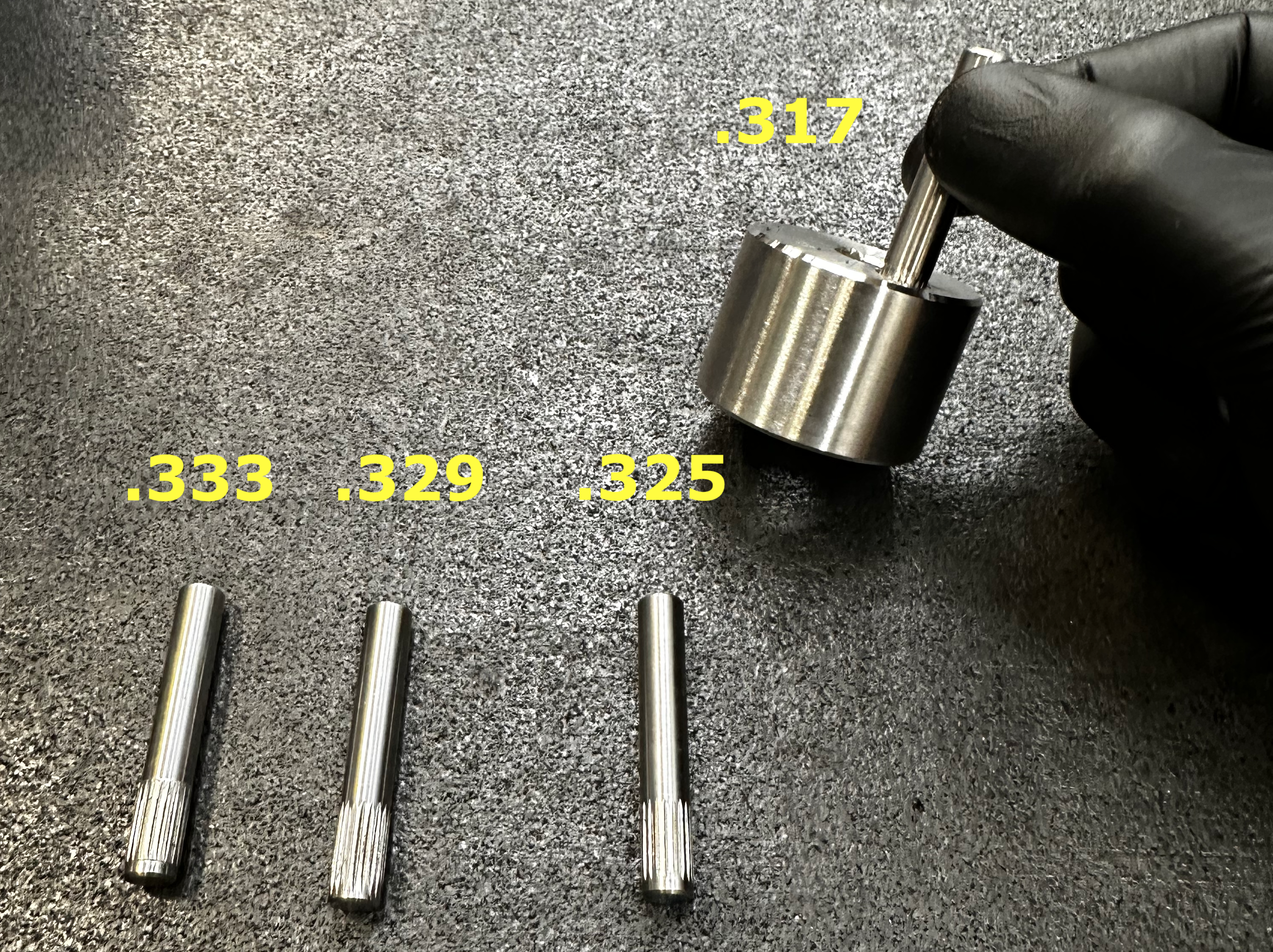
Test each size until the knurling does not fit into the pin hole. This allows for a snug pressing so the pin doesn't fall out under normal operation.
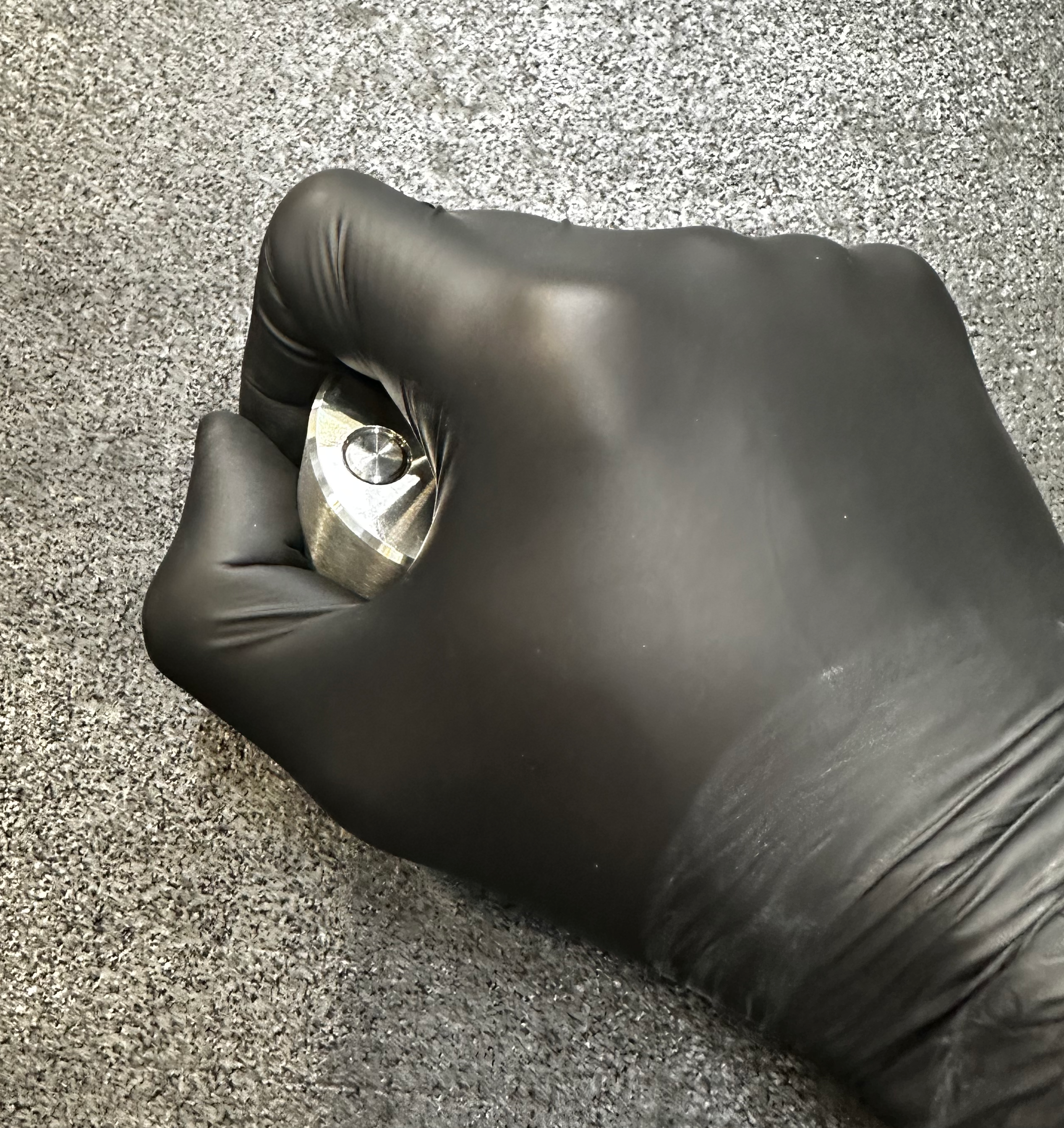
The back side of the crank is indicated by the location of the set screw. The set screw is closest to the back side of the crank.
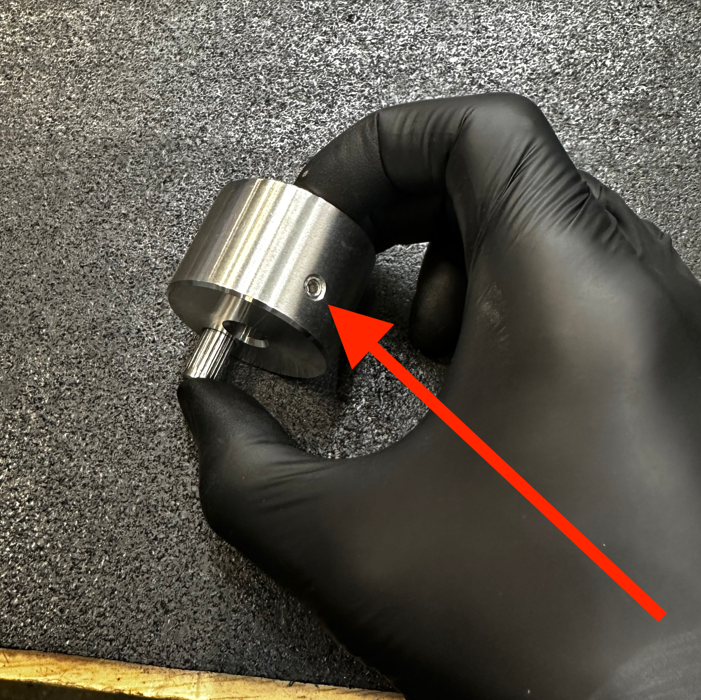
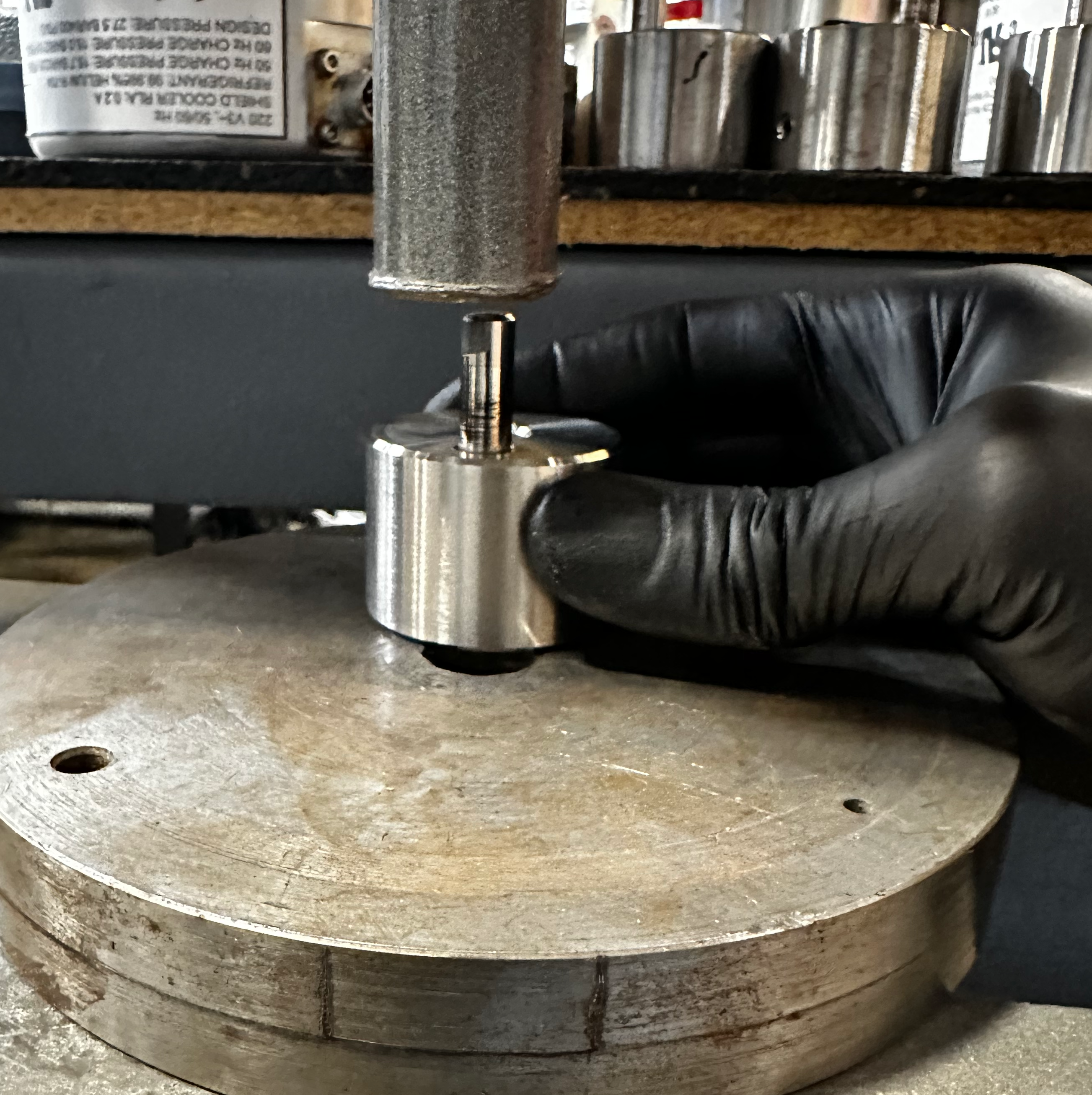
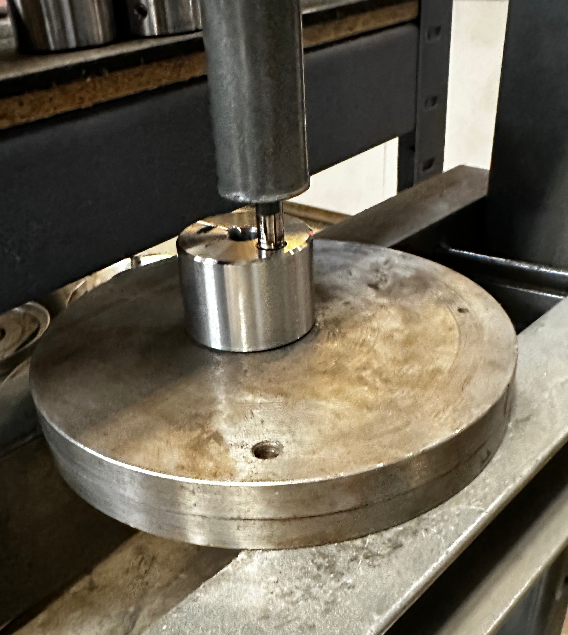
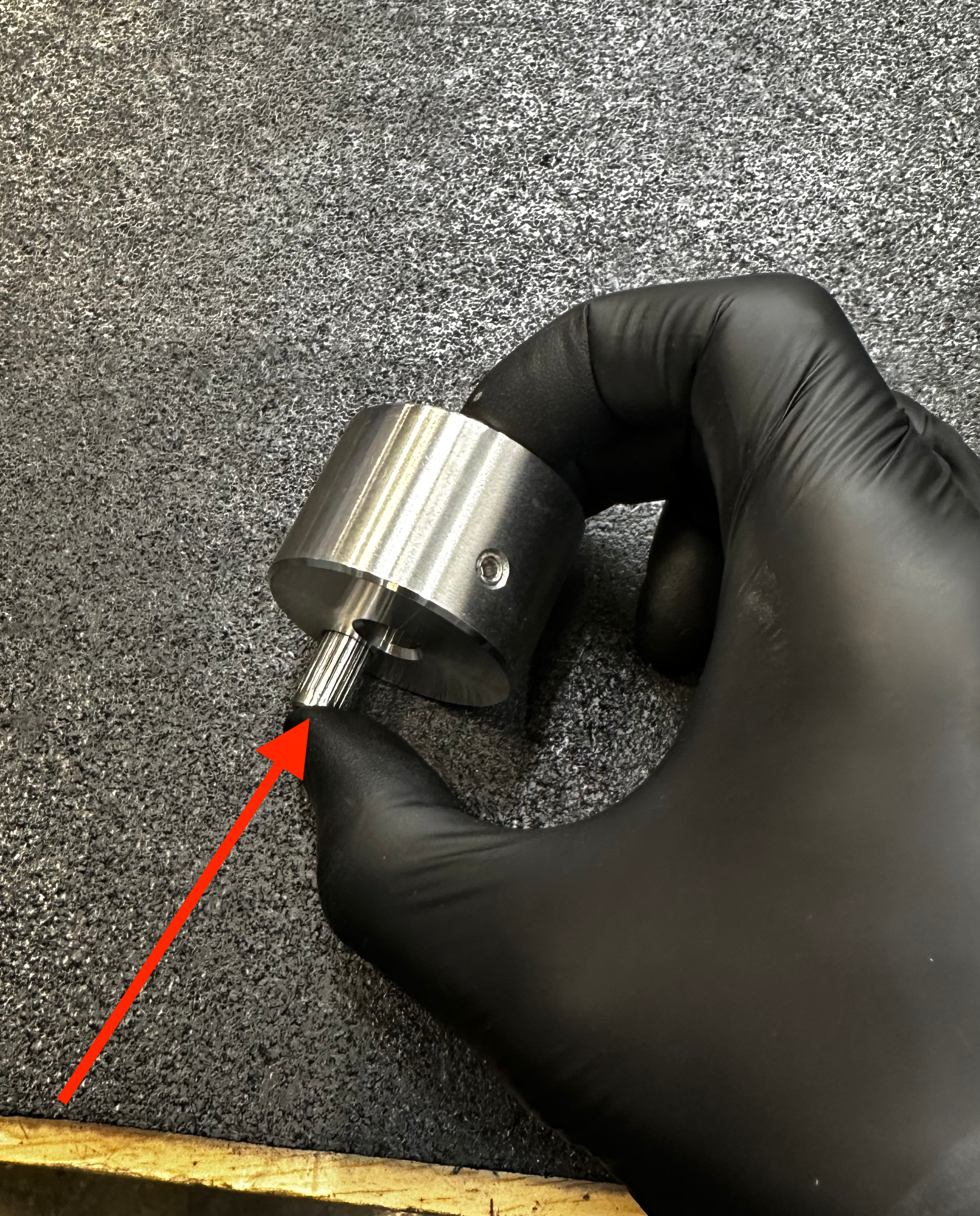
Insert the finished side of the pin through the back side side of crank. The pin should stop when the knurling reaches the crank pin hole. If the pin falls through go to the next size up.
Press crank pin in using the arbor press. The pin should go in with medium pressure.
Testing the Pin Tension
Test the pin fit tension by forcefully tapping crank pin side down on Rubber coated bench top.
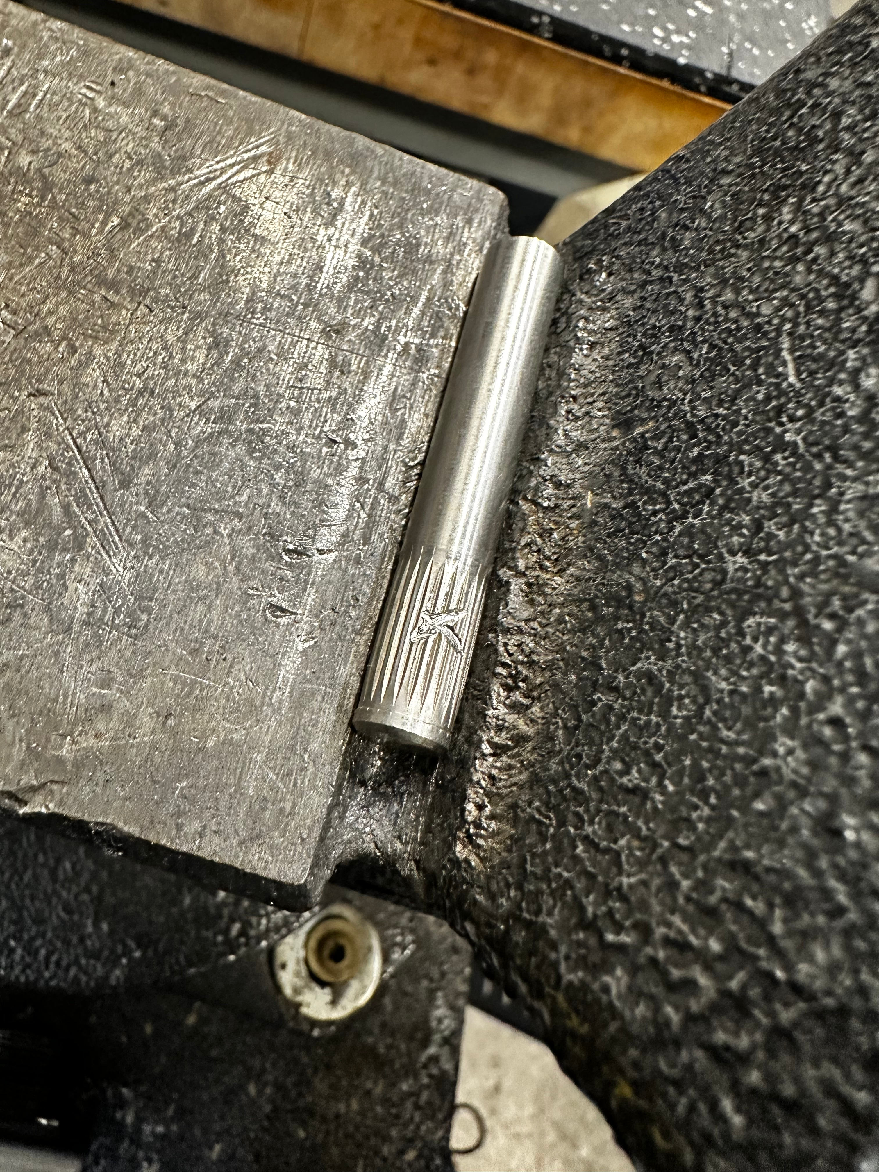
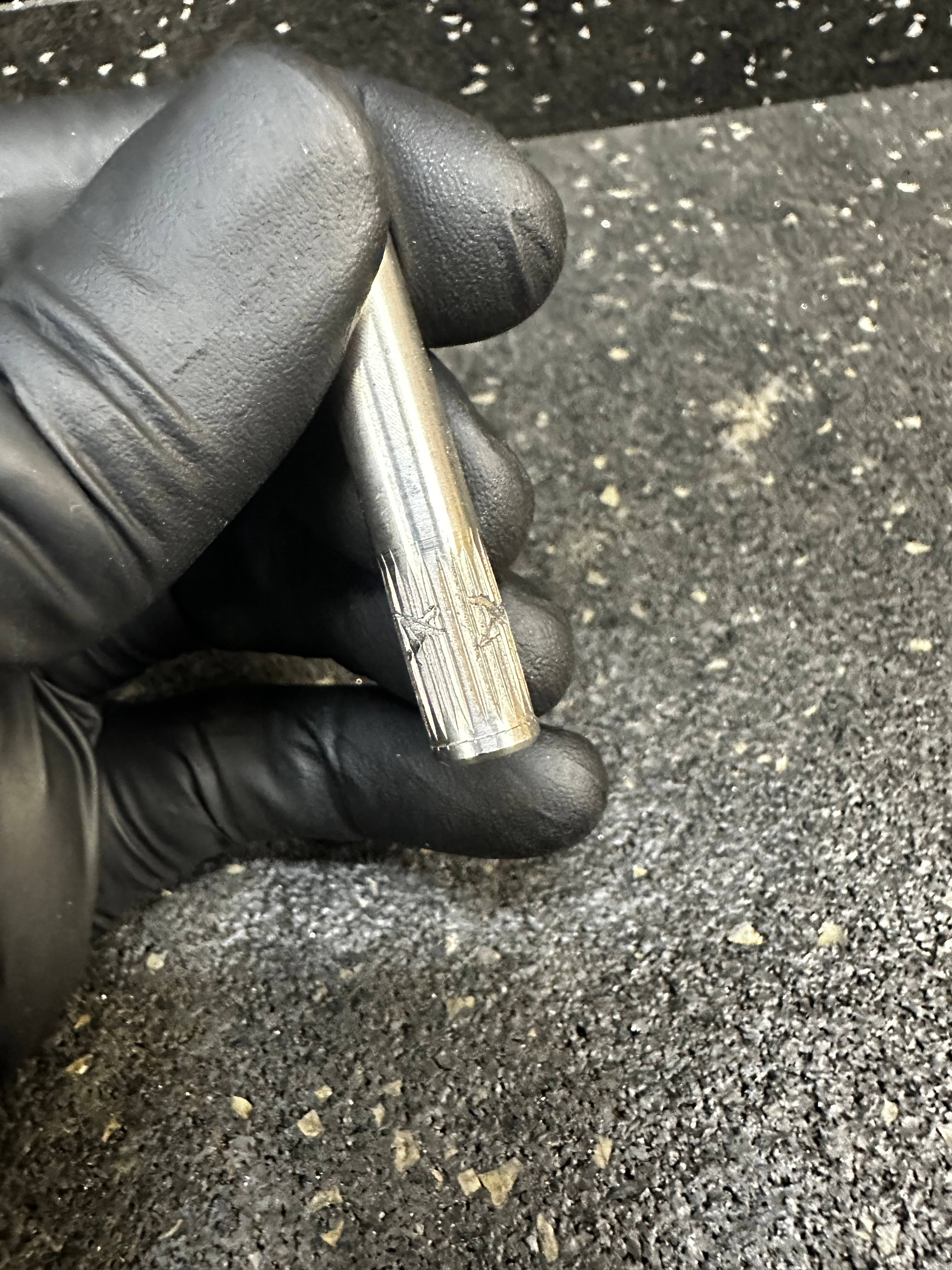
If the pin moves, remove it using the arbor press and use the chisel to peen an X shape on 2-3 locations of the knurling.
Danger
Wear eye protection when using striking tools to prevent a potential eye injury. The striking tool or hammer may chip or break causing projectile metal.
Cradle the pin in the crevice on the vice anvil.

Repeat the Testing the Pin Tension instructions until the pins stays tight during the tap test.
Place complete crank in repair bin for later installation.
Disassembling the Motor
This stage of the procedure involves the complete disassembly of the motor components.
End Plate & Bearing Removal
Crank Plate Removal
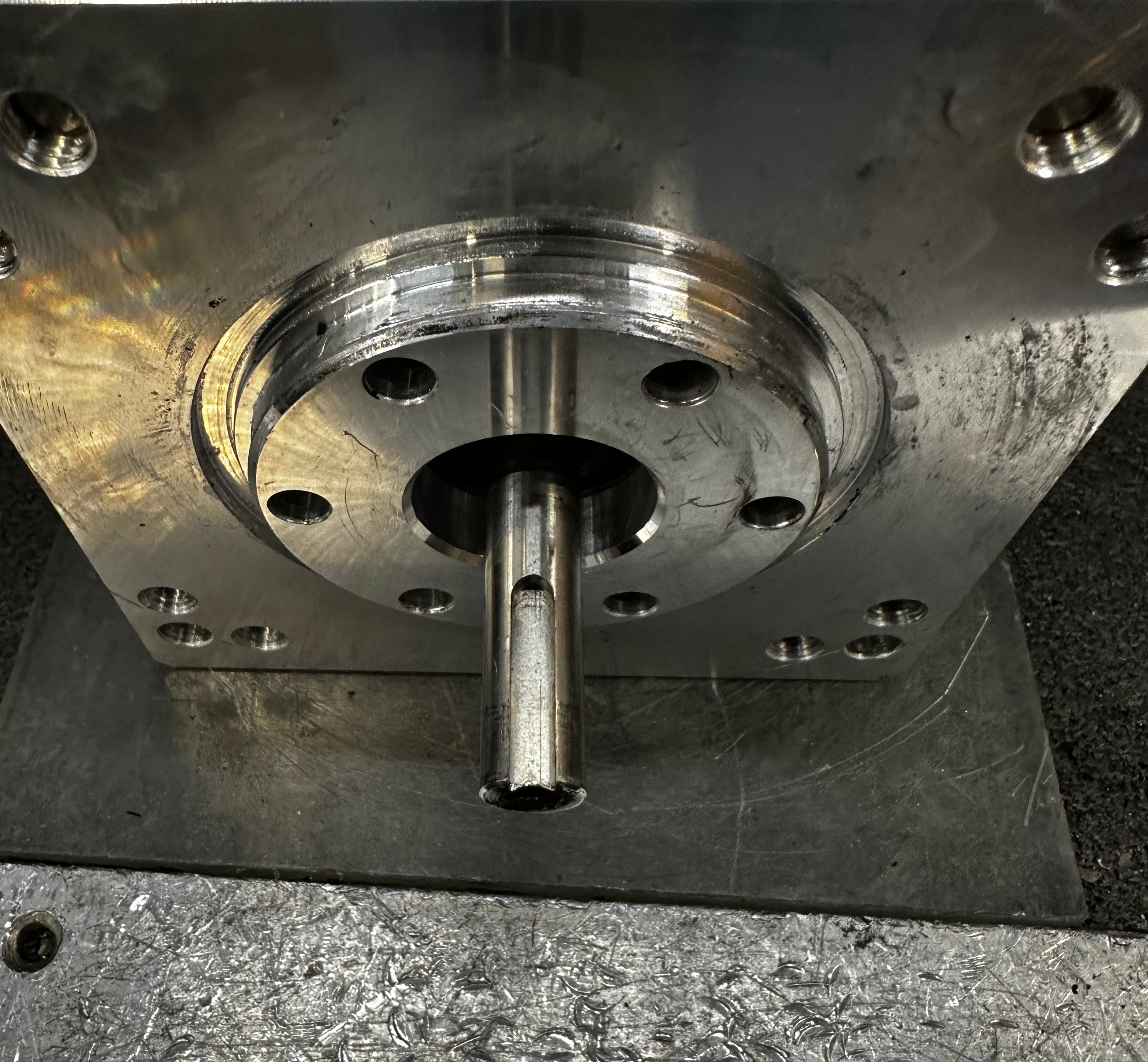
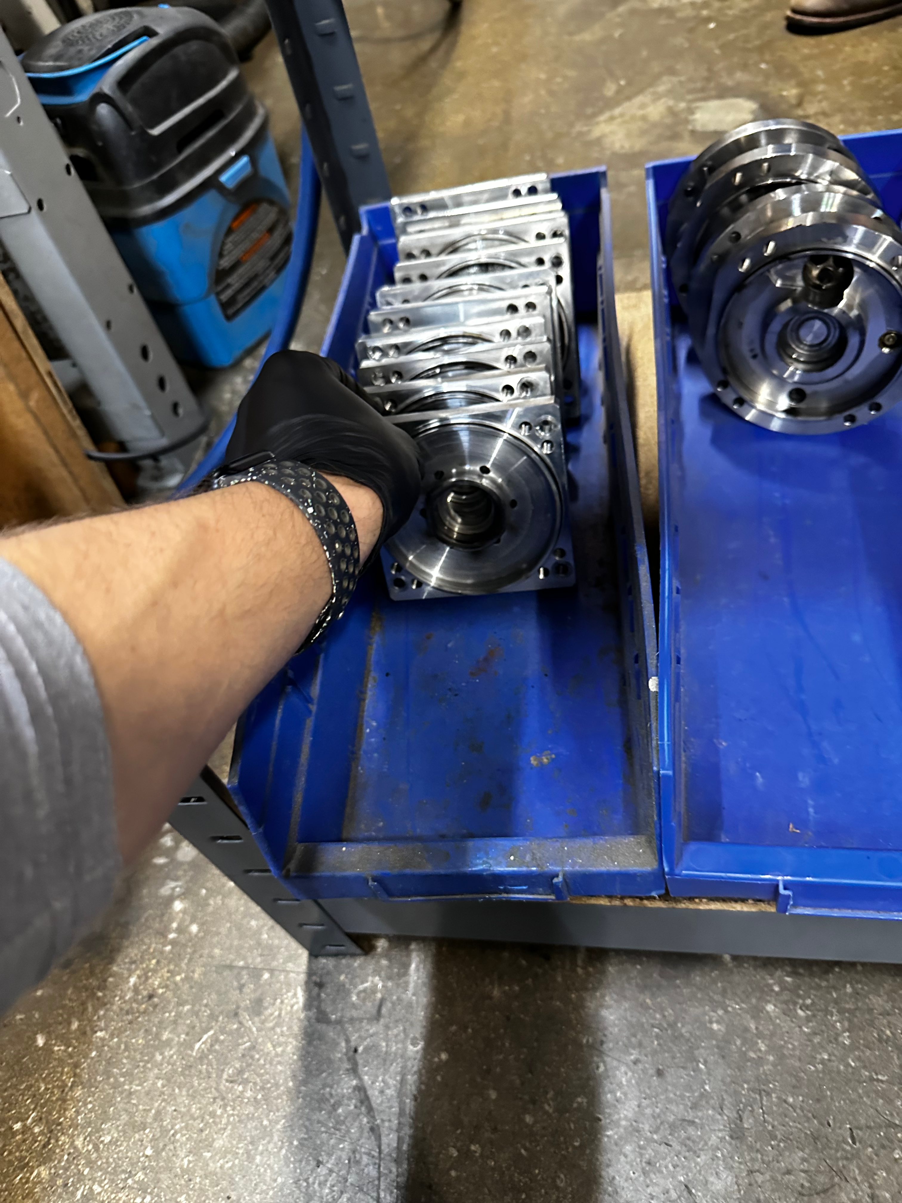
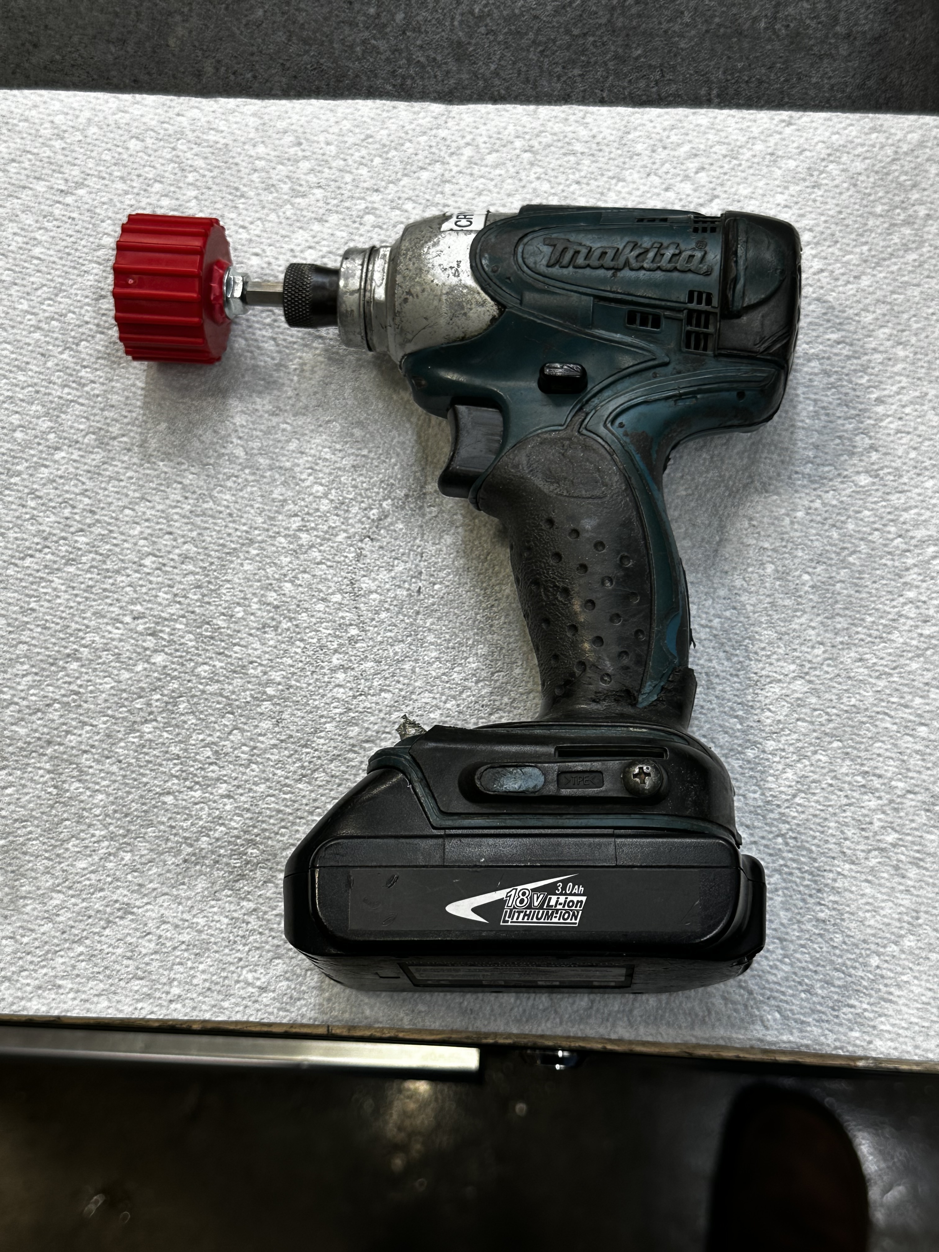
Remove 8 x M6 motor bolts with 5mm hex key on impact driver in a star pattern and place the fasteners in the repair bin.
Place the motor in the front-plate removal fixture with rotor facing towards you.
Using the large 2 jaw puller, begin removing crank plate.
Check to see that the stator is not being pulled along with the crank plate.
Note
You should be able to see a gap forming in between the motor stator and the aluminum front plate.
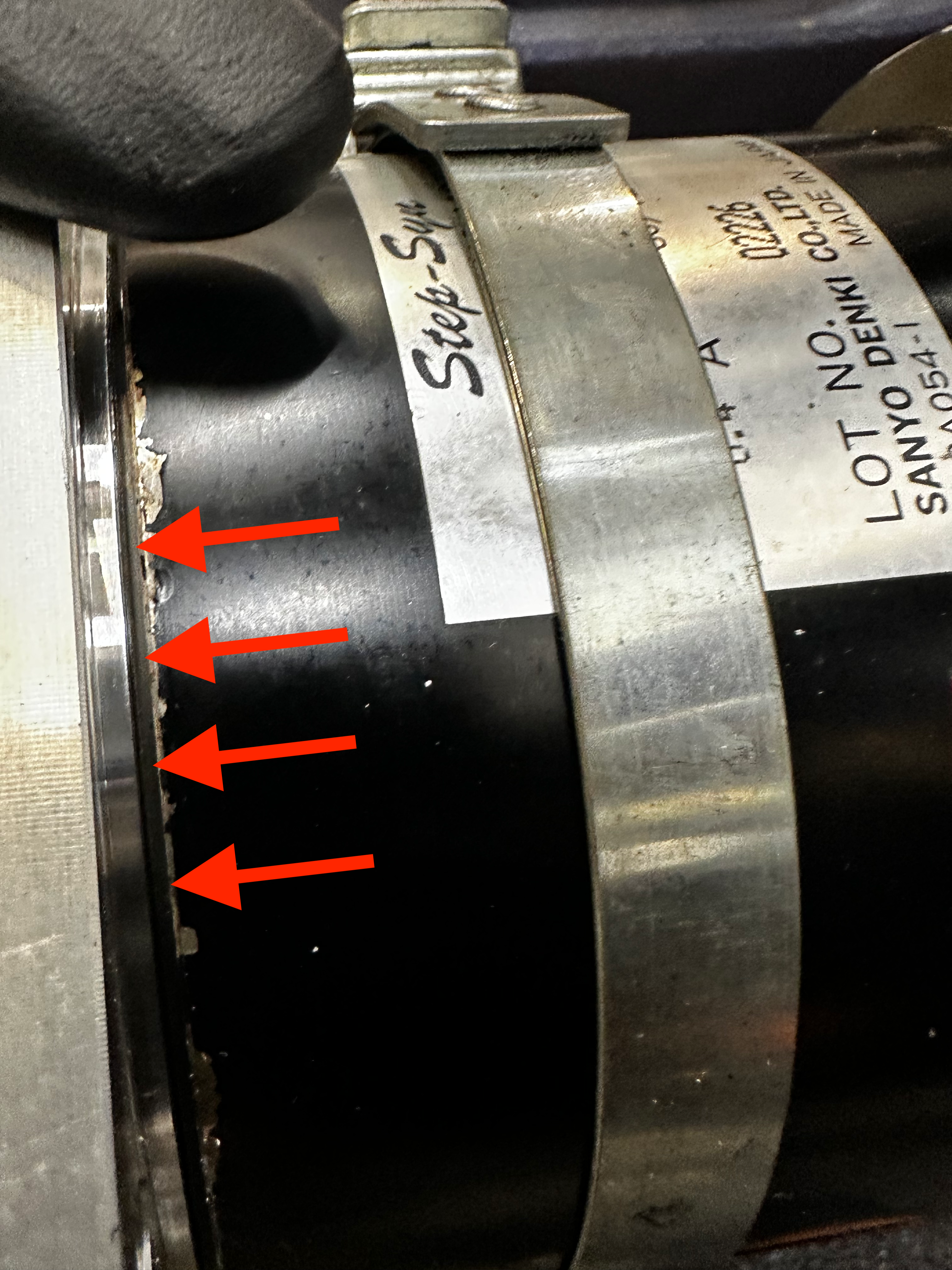
If the stator is coming along with the crank plate, tap the crank plate with mallet until a gap forms.
Note
If the stator is stuck to the crank plate, you will notice separation forming at the back plate.
Place the crank plate in the "to be verified" bin.
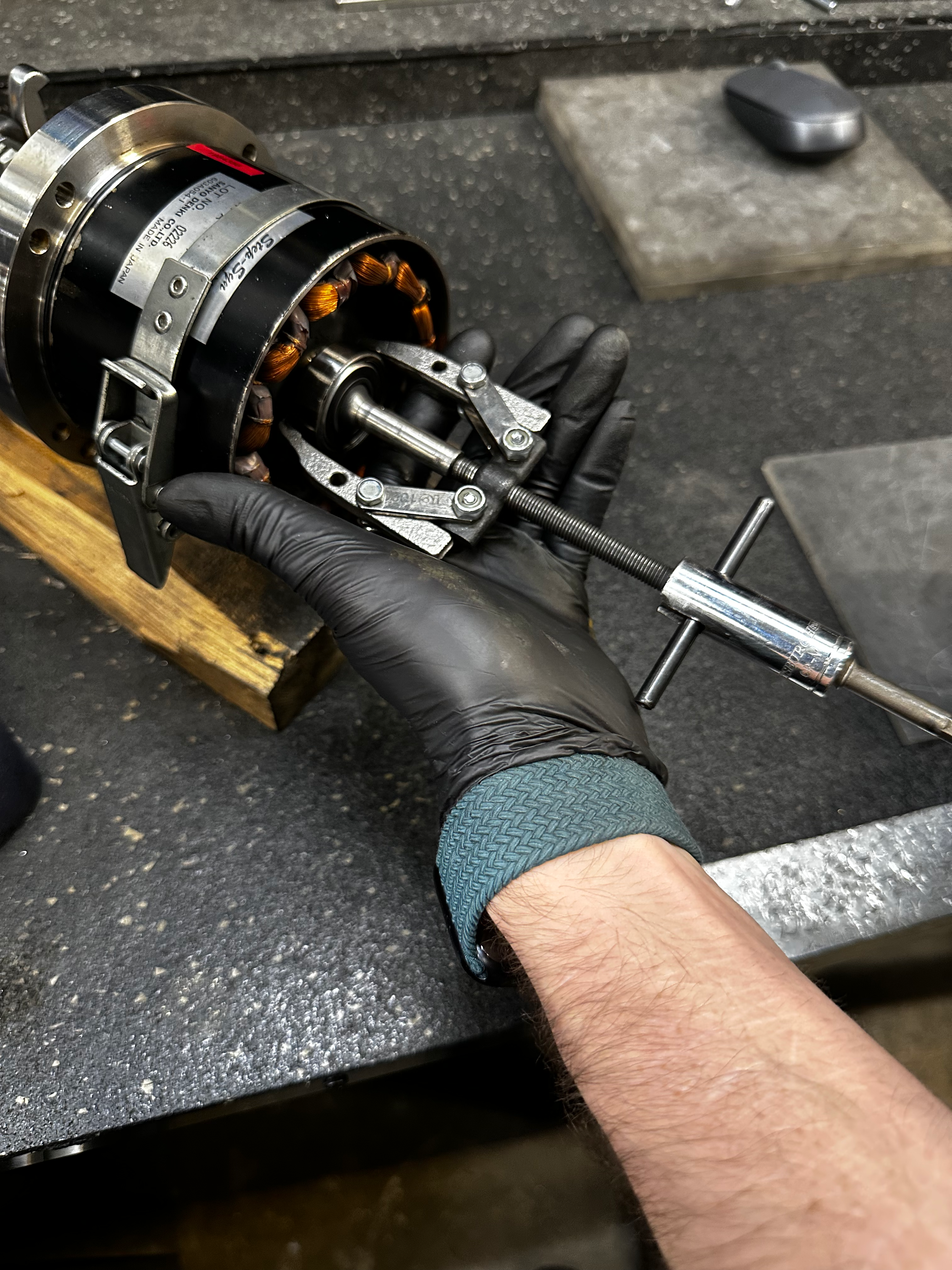
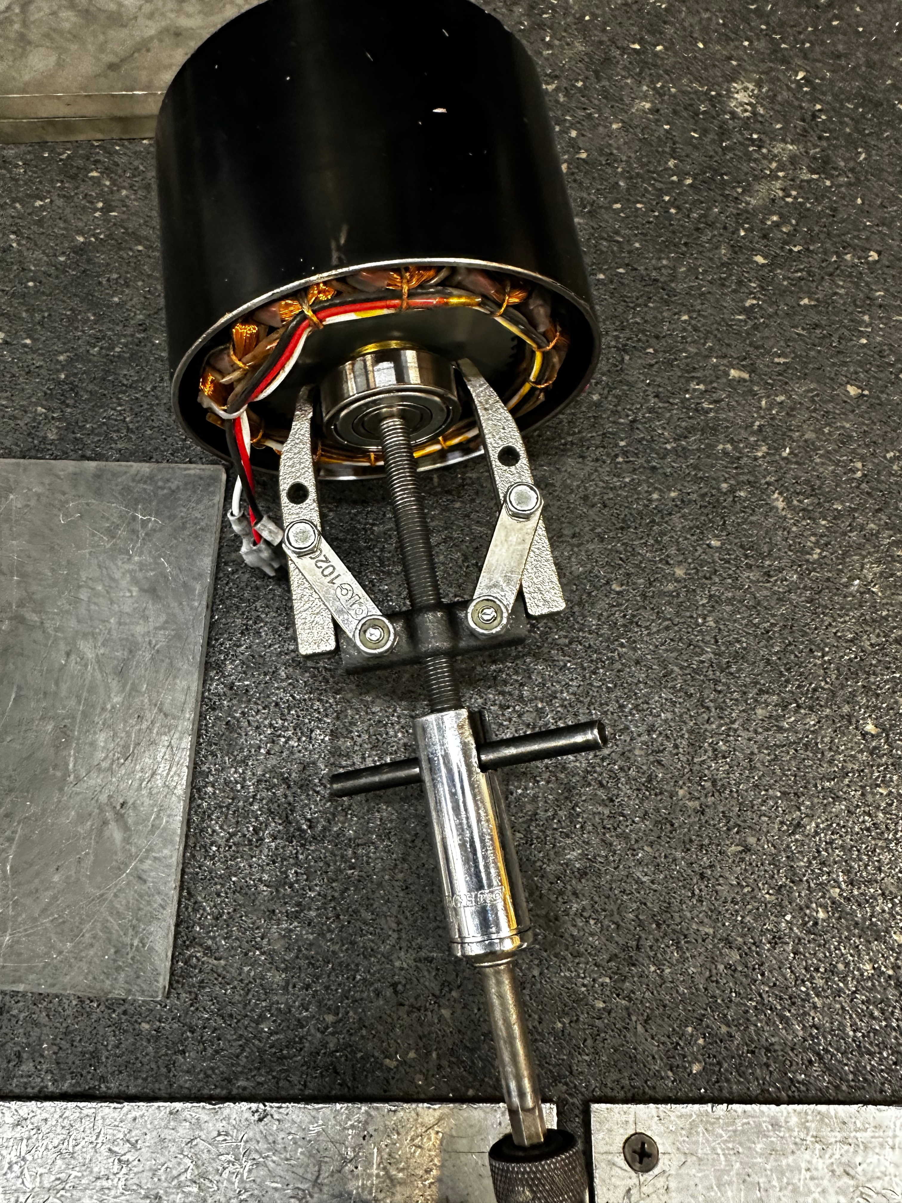
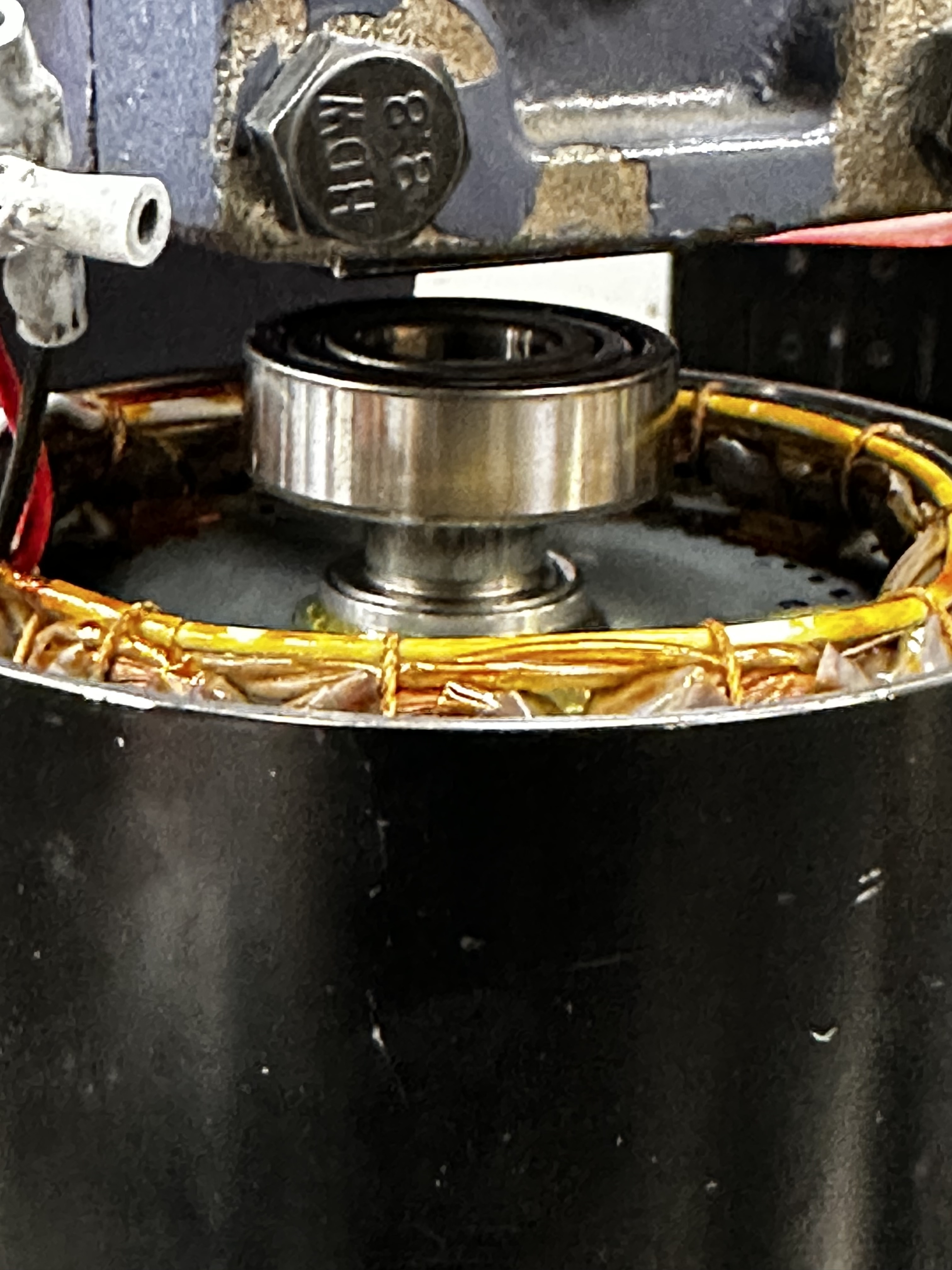
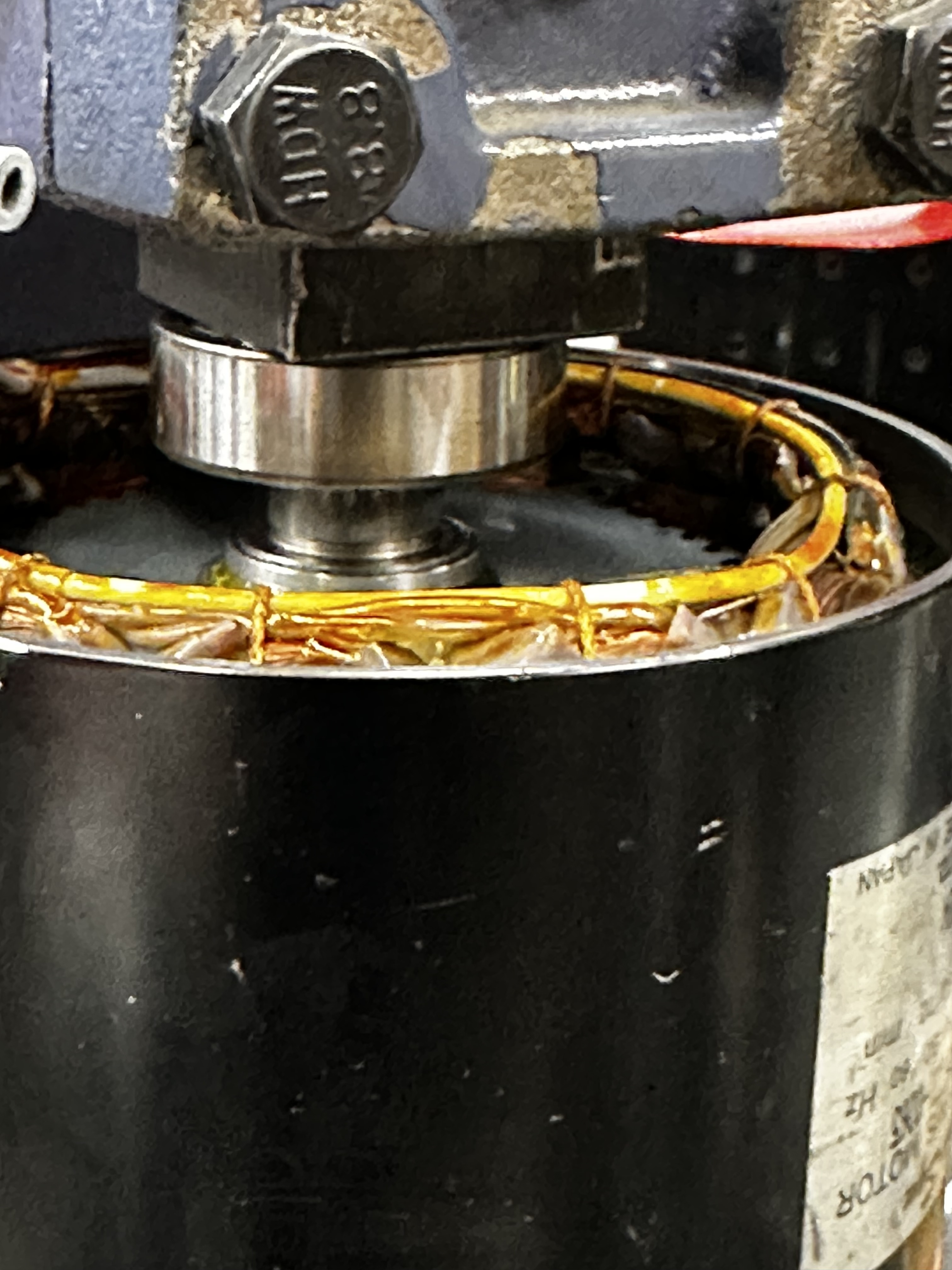
Crank Bearing Removal
Using small 2 jaw puller with the impact driver, remove crank side bearing and recycle it.
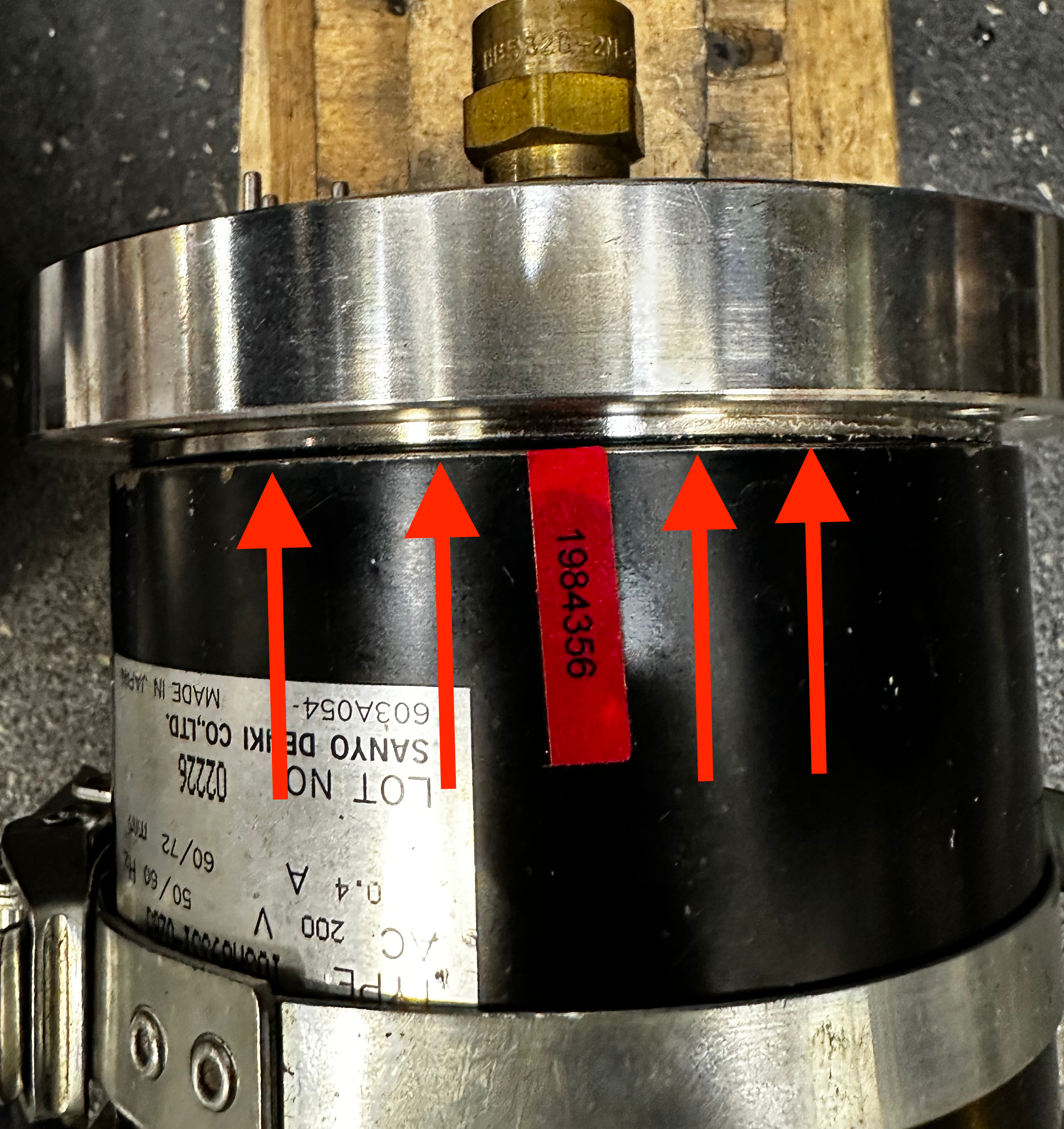
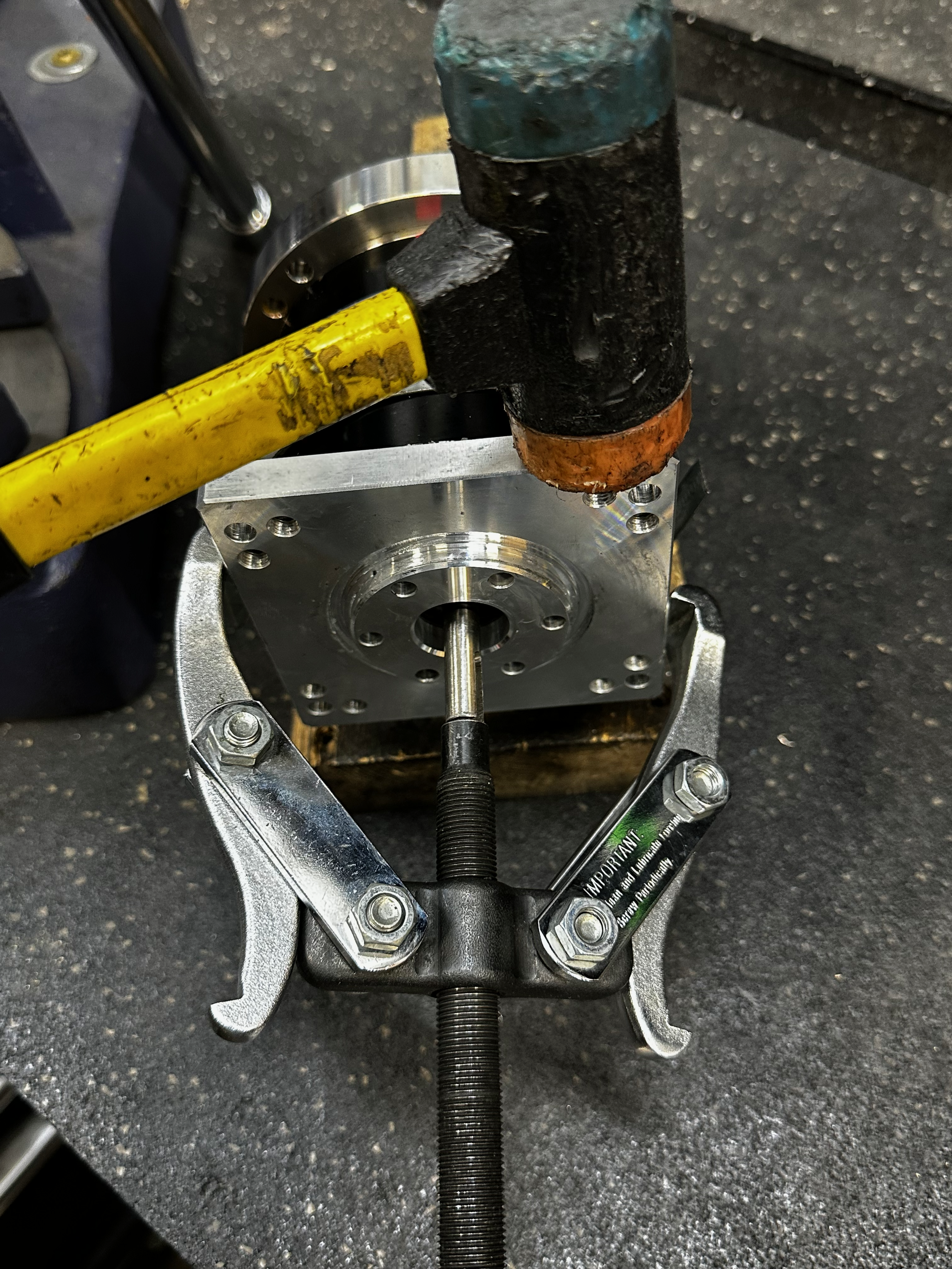
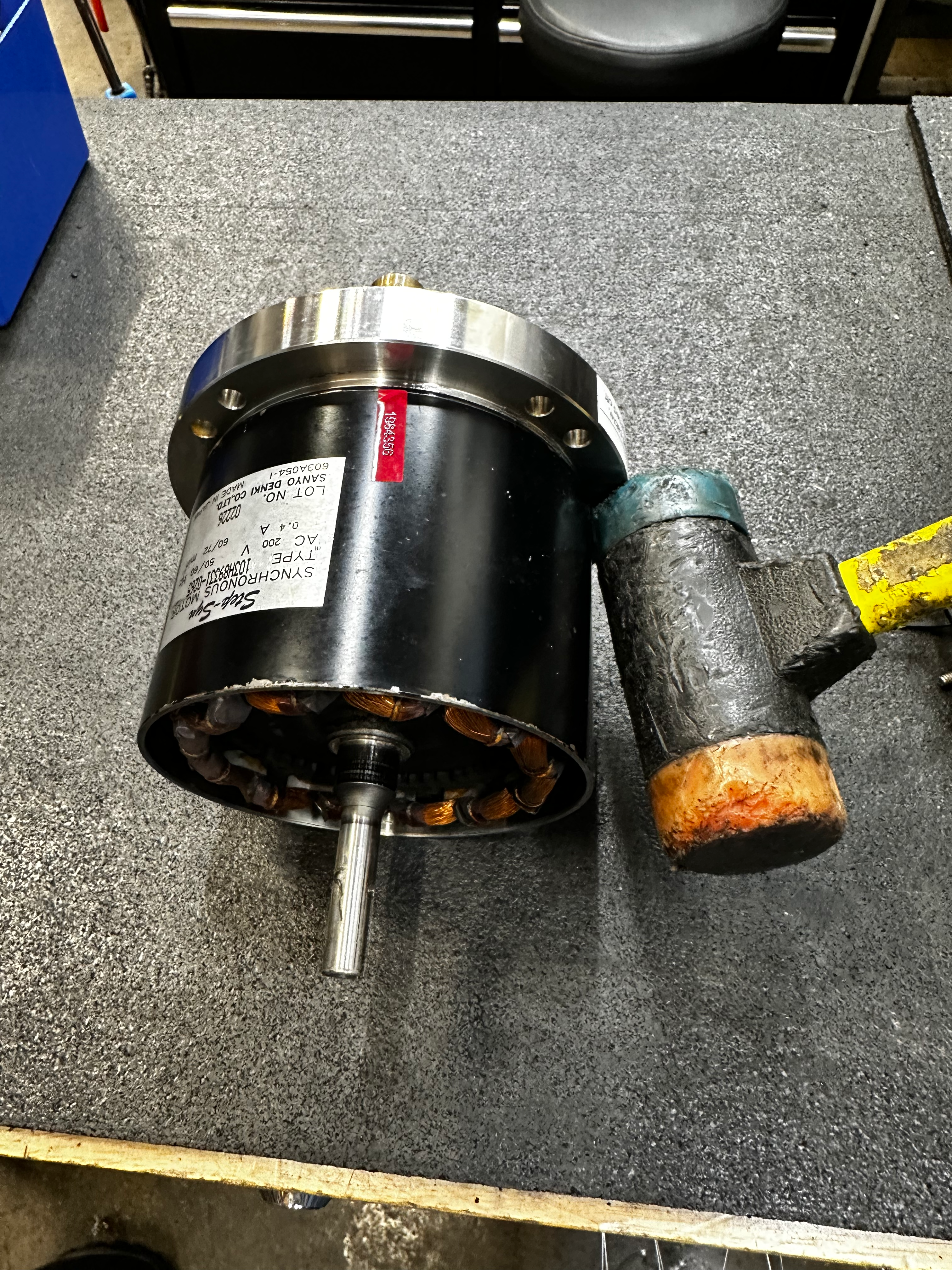
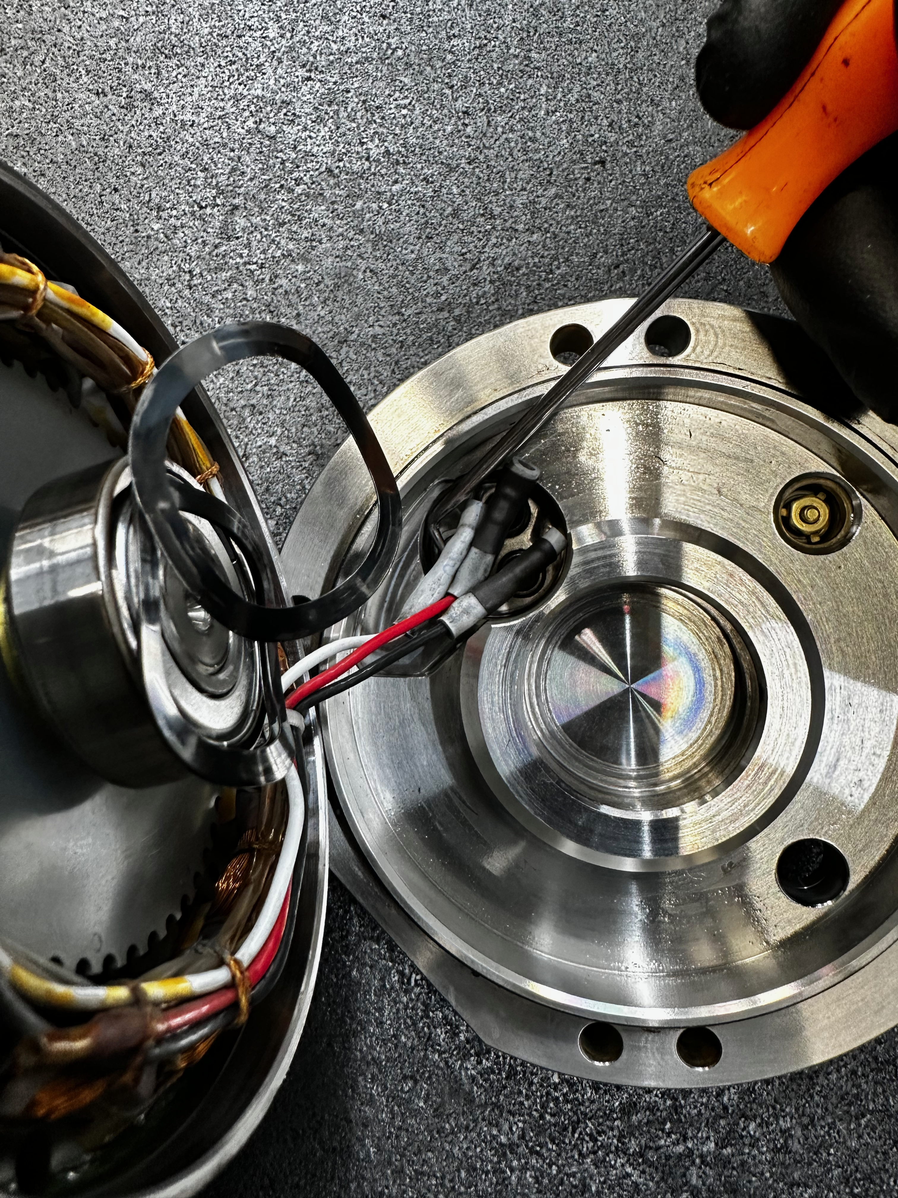
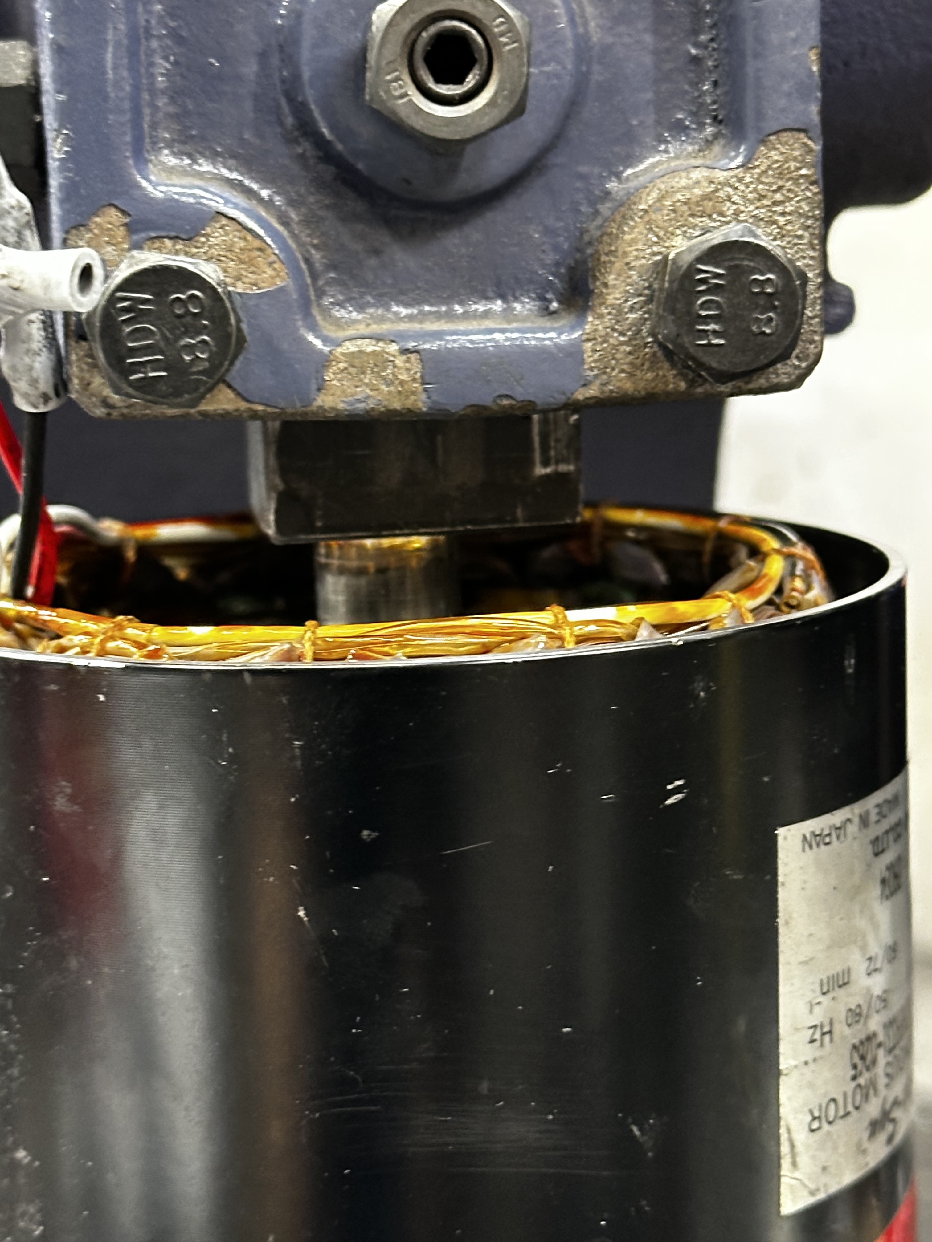
Back Plate Removal
Remove the motor from the fixture to access the back plate. Using the rubber mallet, tap the lip of the back plate alternating sides with each strike.
Note
The electrical connections are short and can be damaged if the back plate tugs on the wires. Once the back plate is free from the stator, slowly rotate the plate to expose the connections.
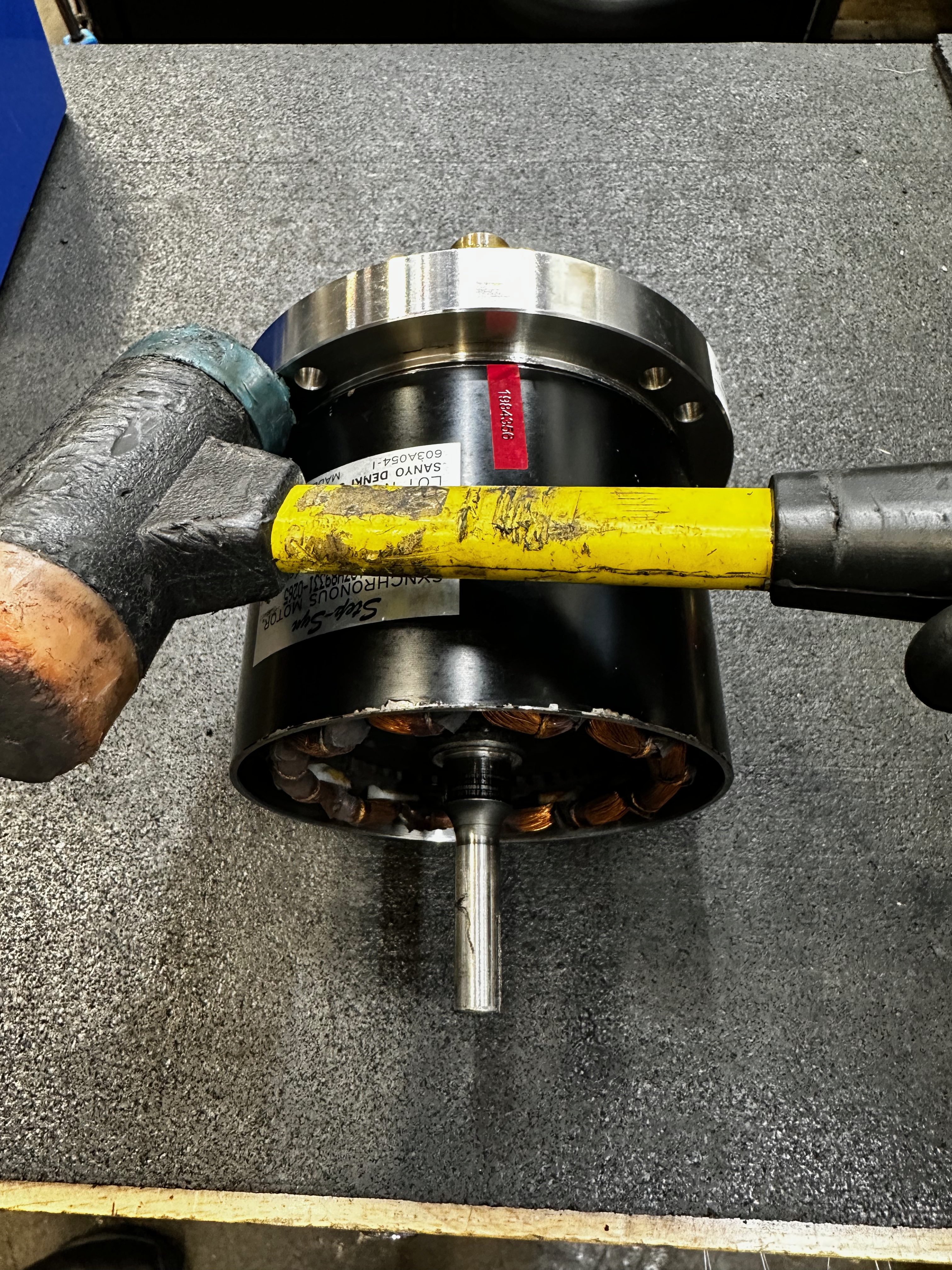
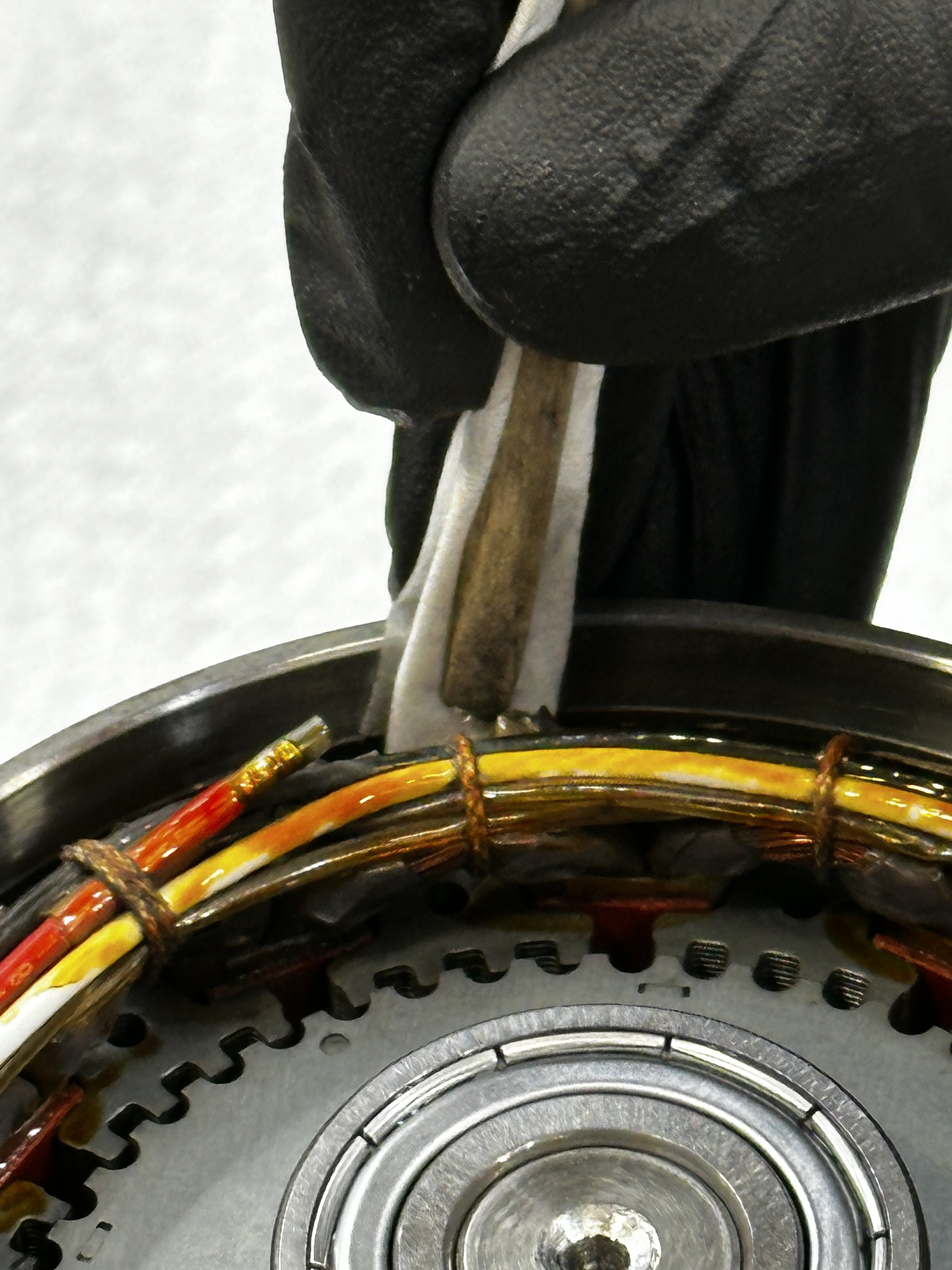
After the back plate comes loose rotate the plate to expose the spade connections.
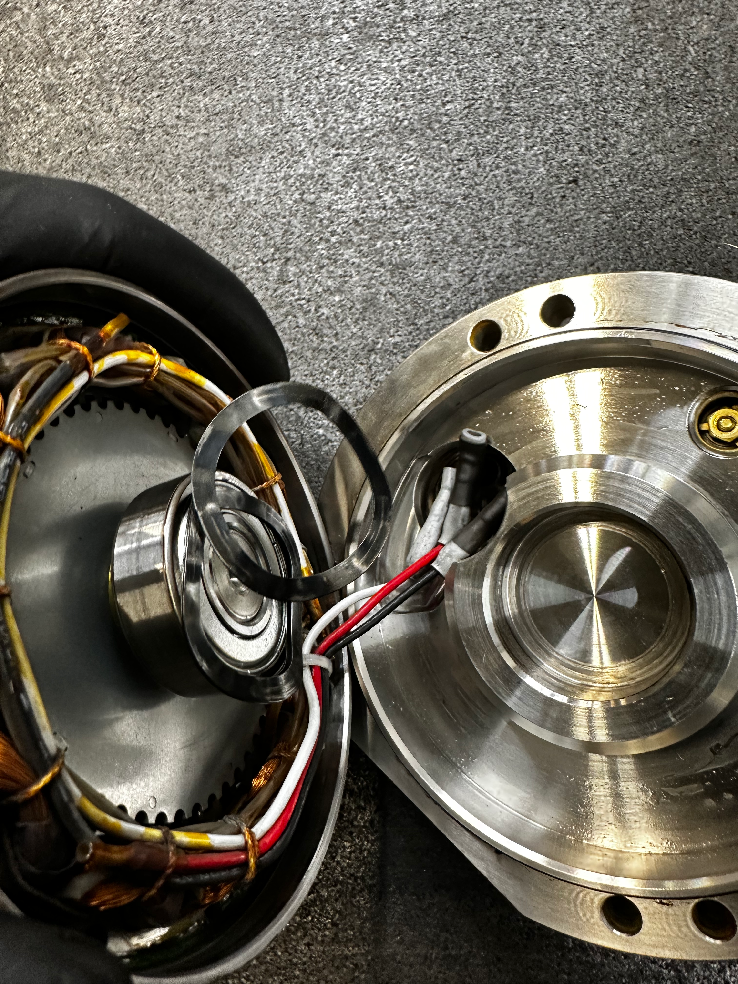
Use a metal hooked pic to slide the spade connectors from the straight terminals.
Back Plate Bearing Removal
Using small 2 jaw puller with the impact driver, remove back side bearing and recycle it.
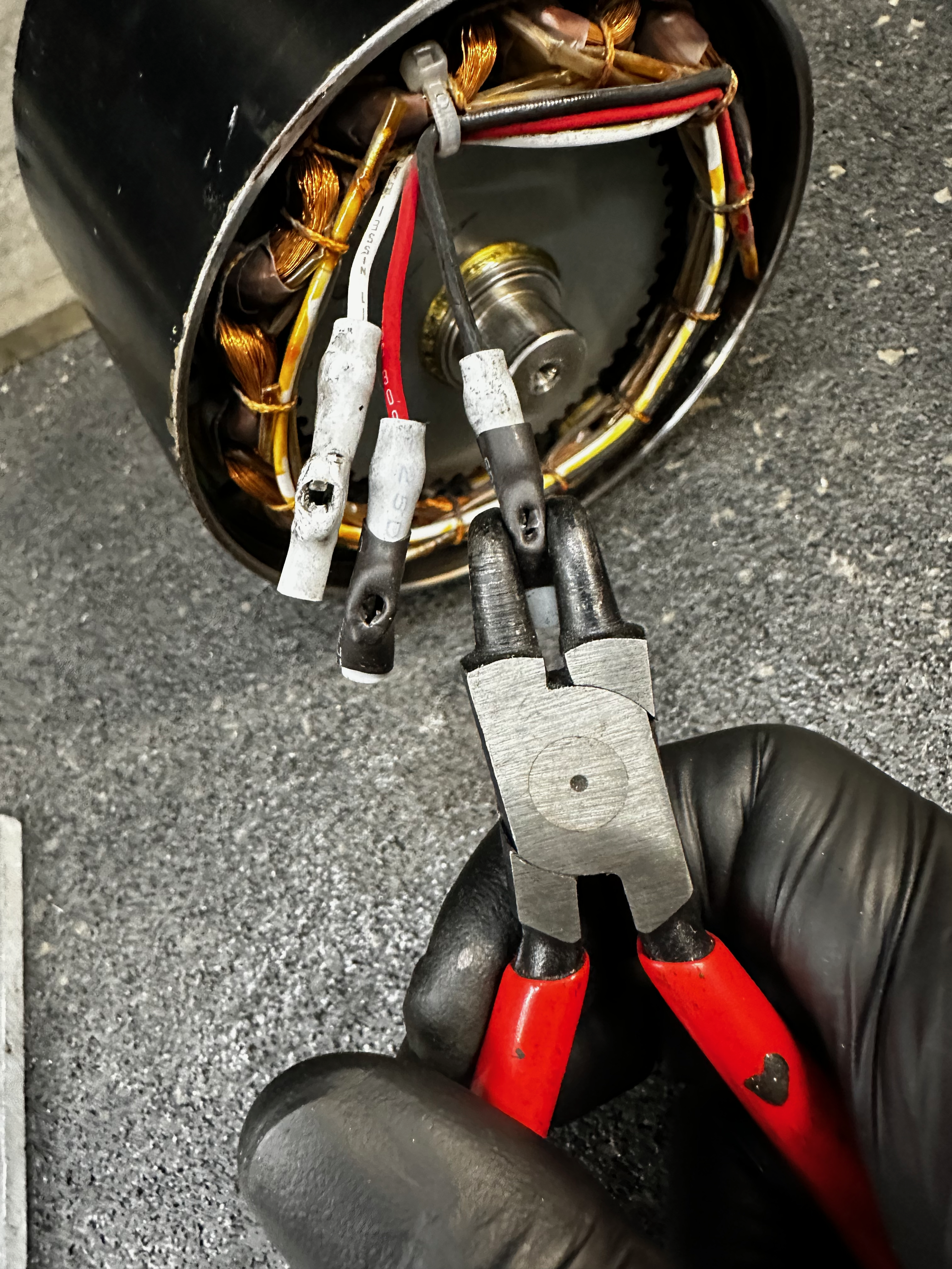
Warning
Over crimping the connectors will damage the connector. Be sure to press lightly.
Using the retaining clip tool, squeeze the electrical connectors on stator to make sure that they will seat the next time they are connected to the terminals.
Cleaning The Motor
Cleaning the Rotor
Clean rotor faces with kim wipes and alcohol.
Tip
Knock the accumulated clumps of dust off with a dry kim wipe into the garbage before applying the alcohol to the face of the rotor.
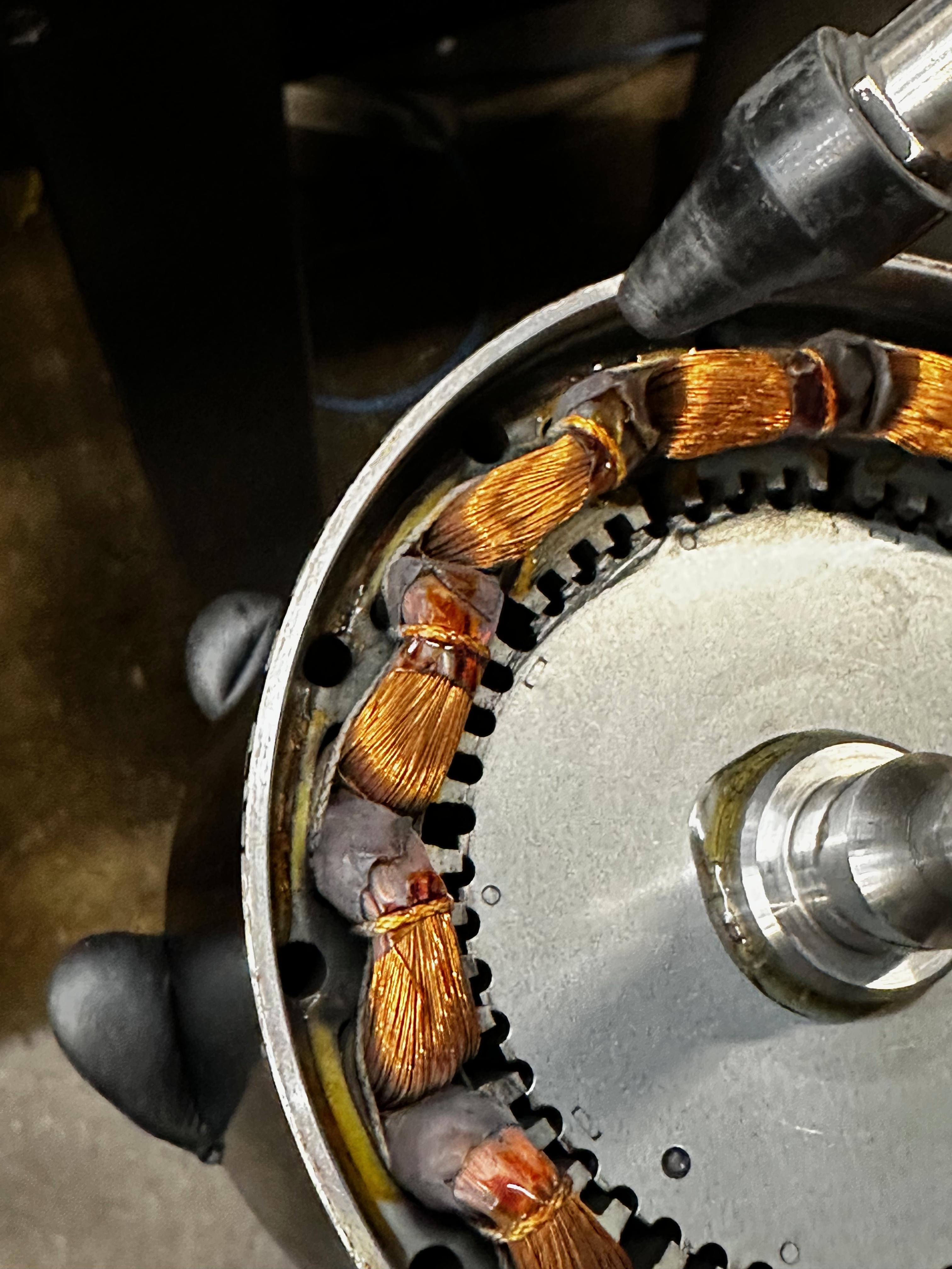
Cleaning the Stator
Blow air gently between the roto and the stator.
Warning
Damaging the insulation on the windings will cause an electrical short. Be careful not to come into contact with the windings with anything.
Blow air through stator holes.
New Bearing installation
Crank Bearing
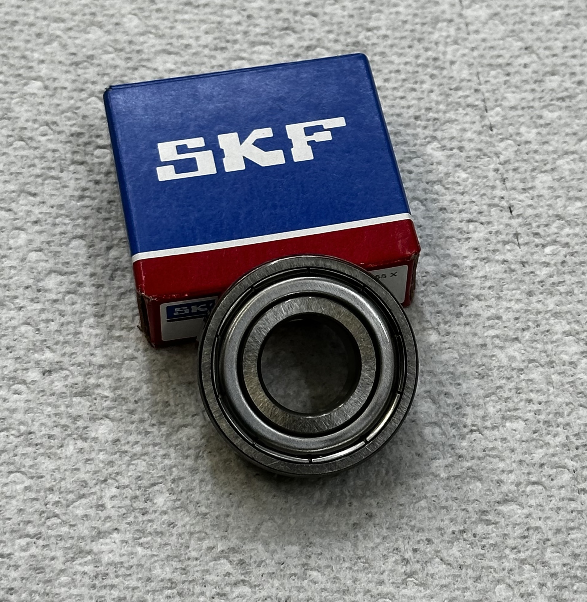
Obtain 2 x 6202-2Z bearings
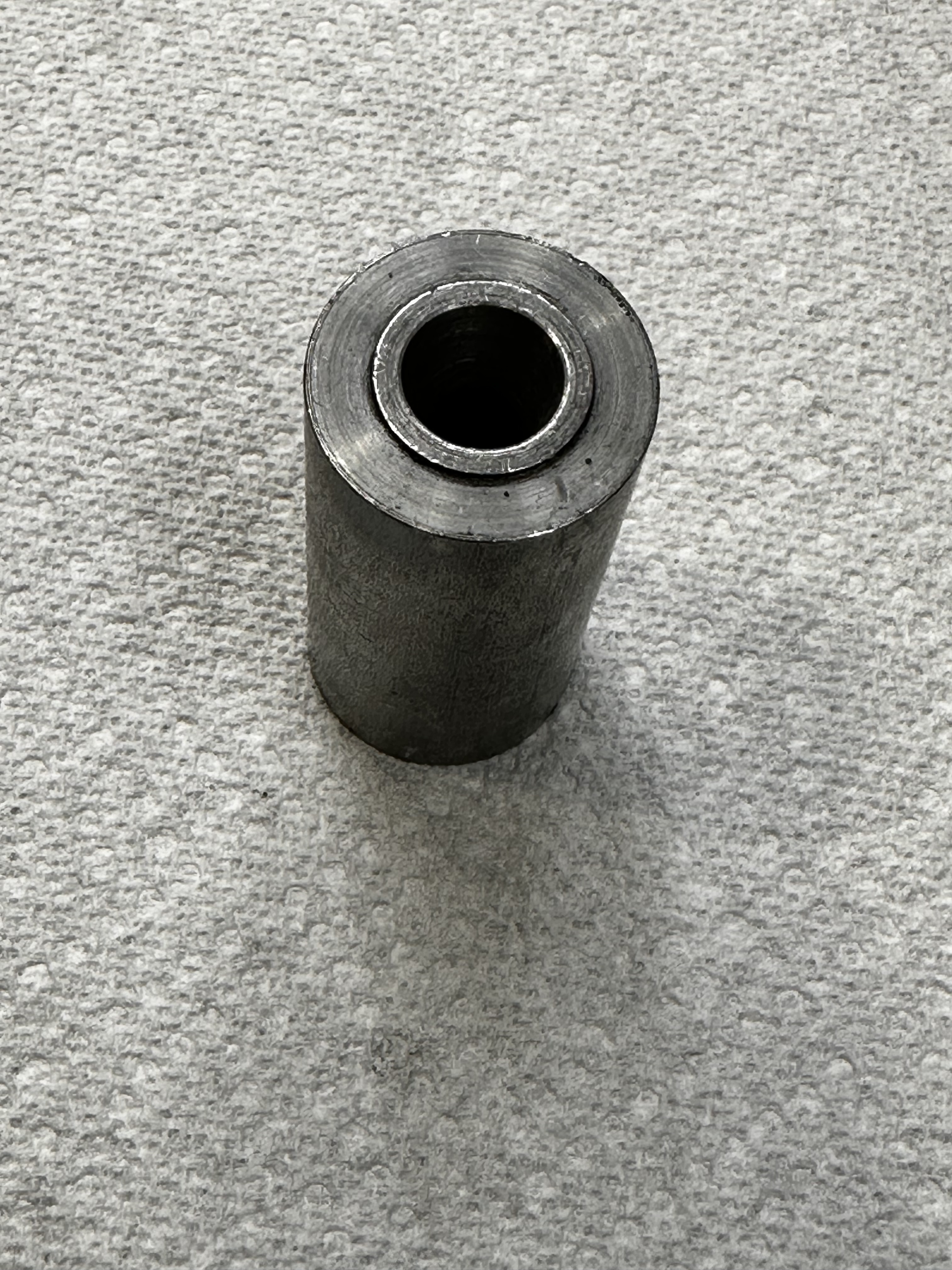
Place a bearing over the shaft of the rotor and slide the bearing mandrel over the shaft of the rotor.
Place the motor in the arbor press with the mandrel side down.
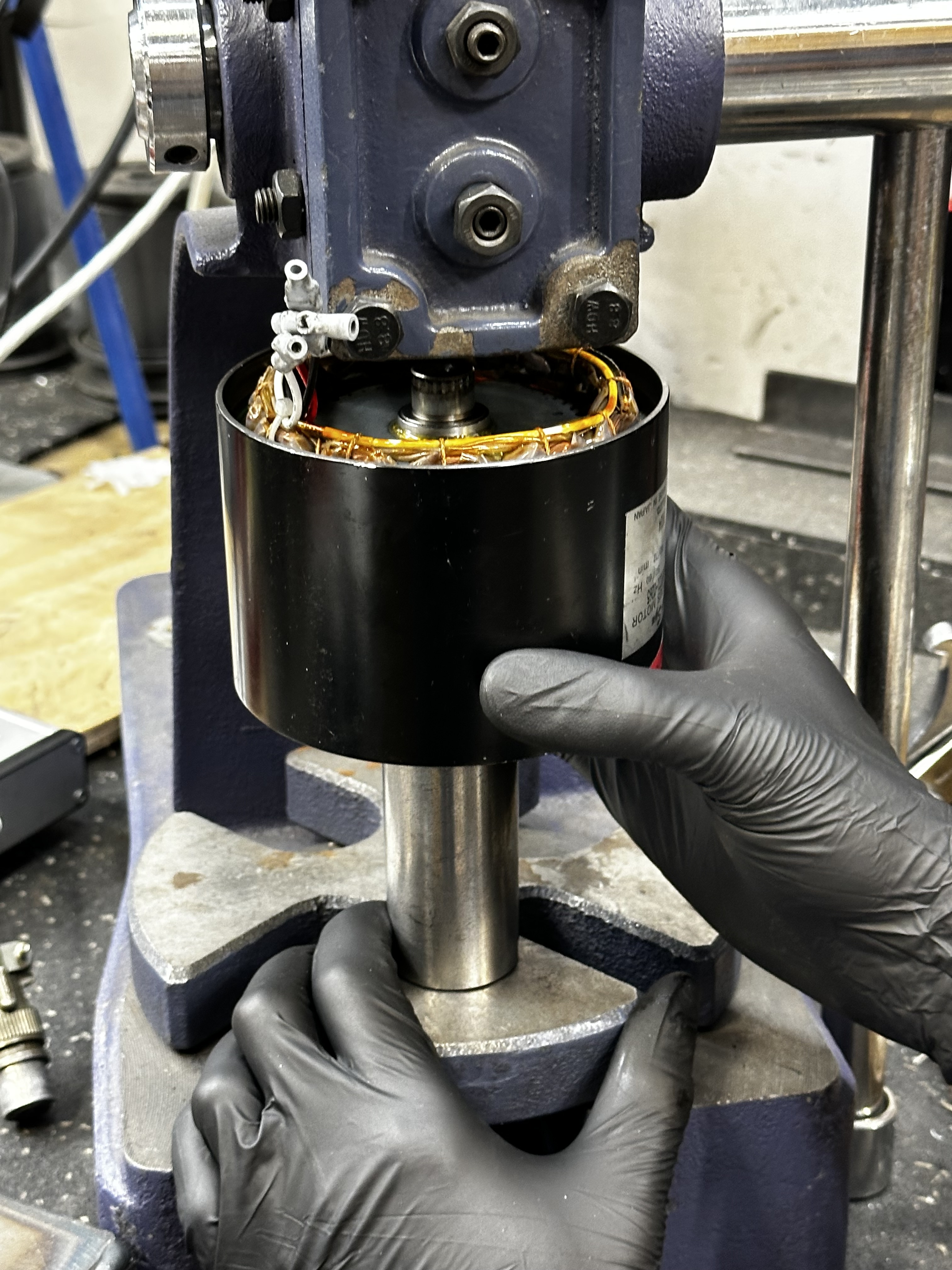
Press down on the back side of the rotor to drive the crank side bearing onto the rotor shaft.
Back-Plate Bearing
In order to press the back-plate bearing onto the rotor you must reinstall the crank bearing mandrel to support the rotor.
Center the bearing on the back of the rotor, align the back-plate bearing mandrel over the bearing and press it into position using the arbor press.
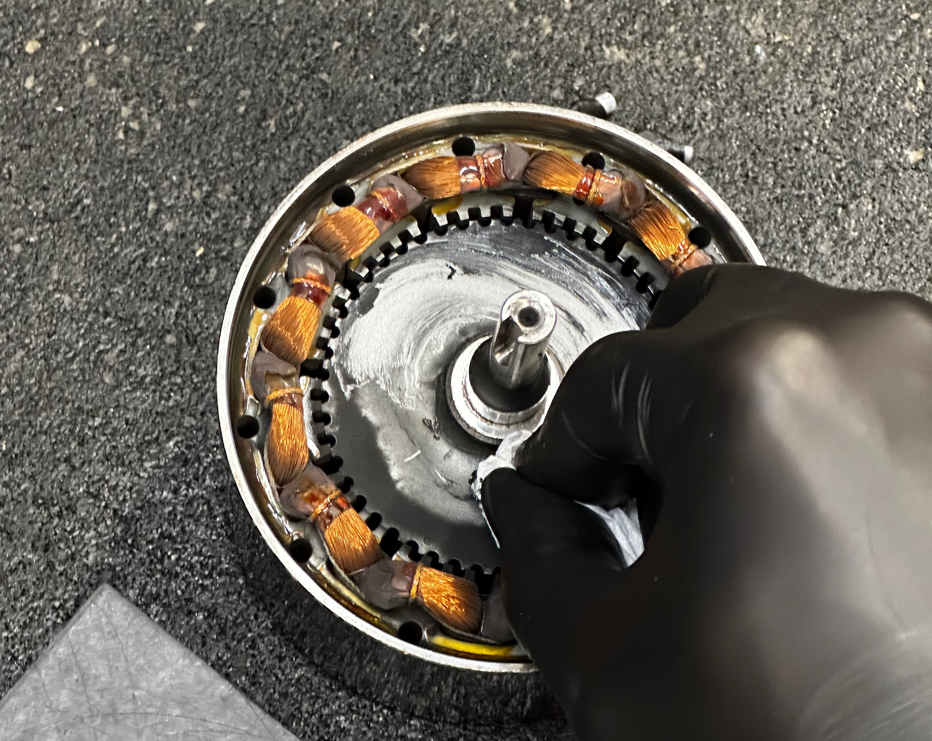
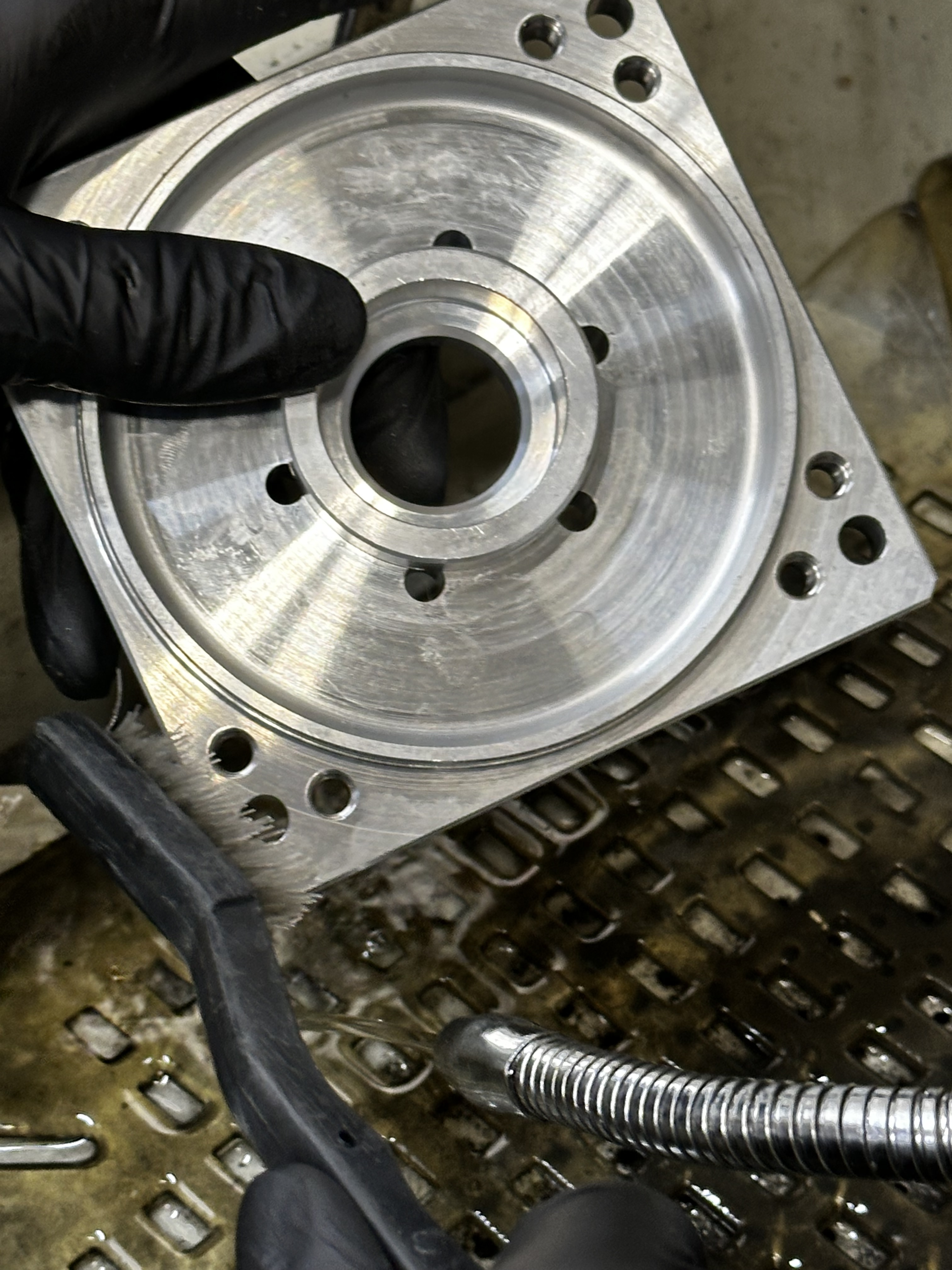
Clean O-ring Surfaces
Place the motor in the PVC cleaning fixture with the crank side down.


Warning
This process involves bringing tools close to the motor windings. Coming into contact with the windings will damage them and the motor. Scratching the varnish off will cause permanent damage.
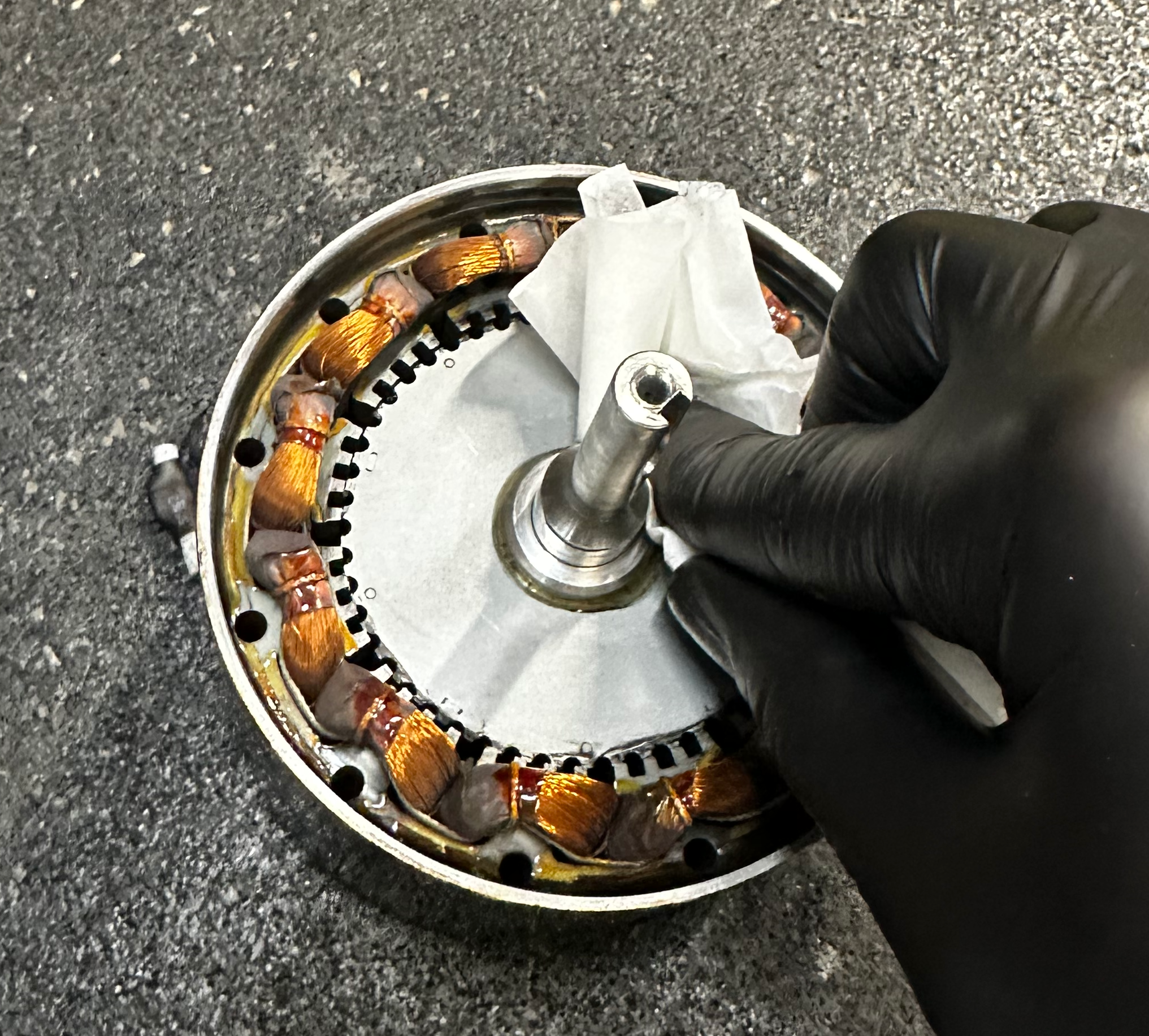
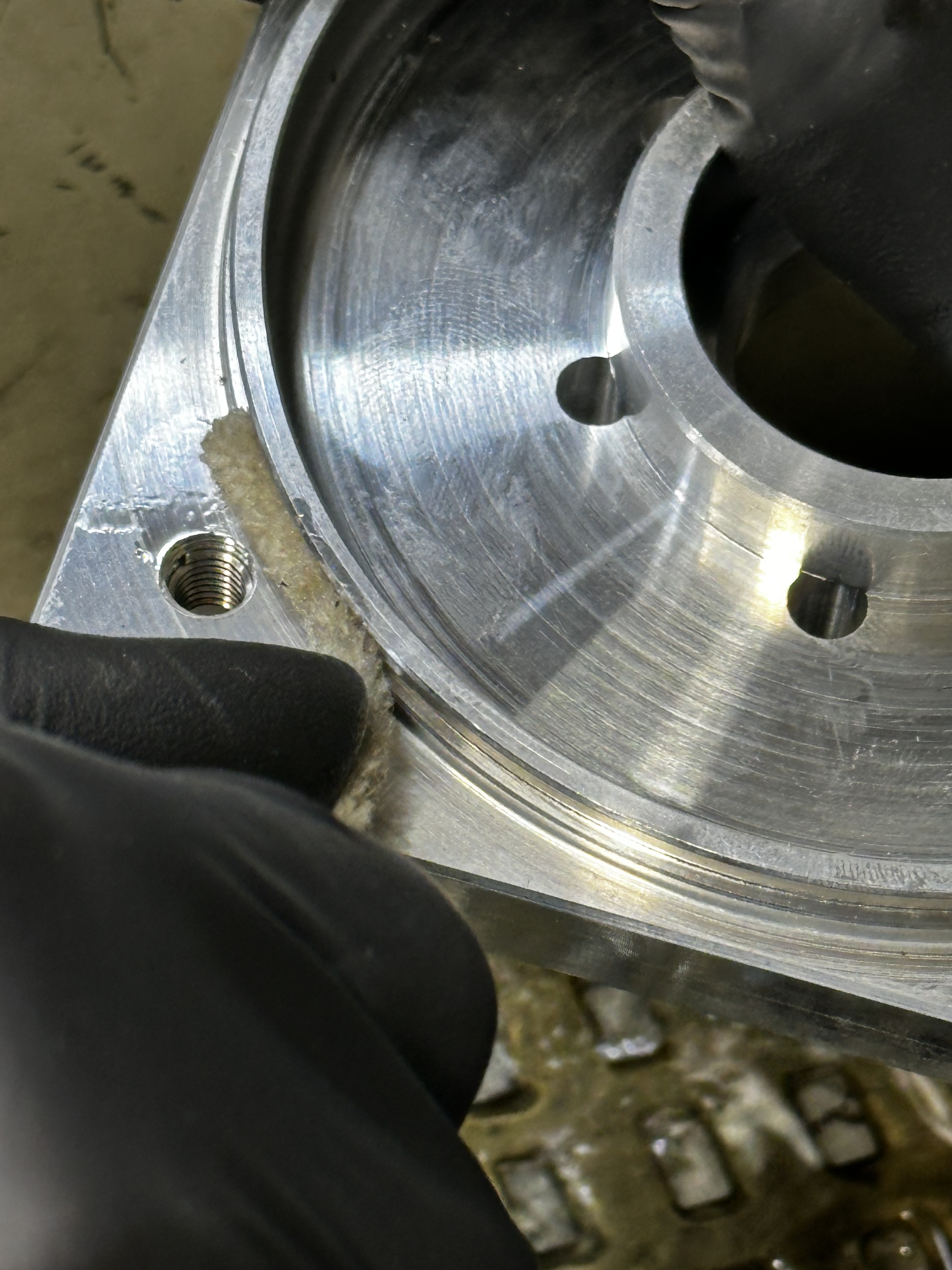
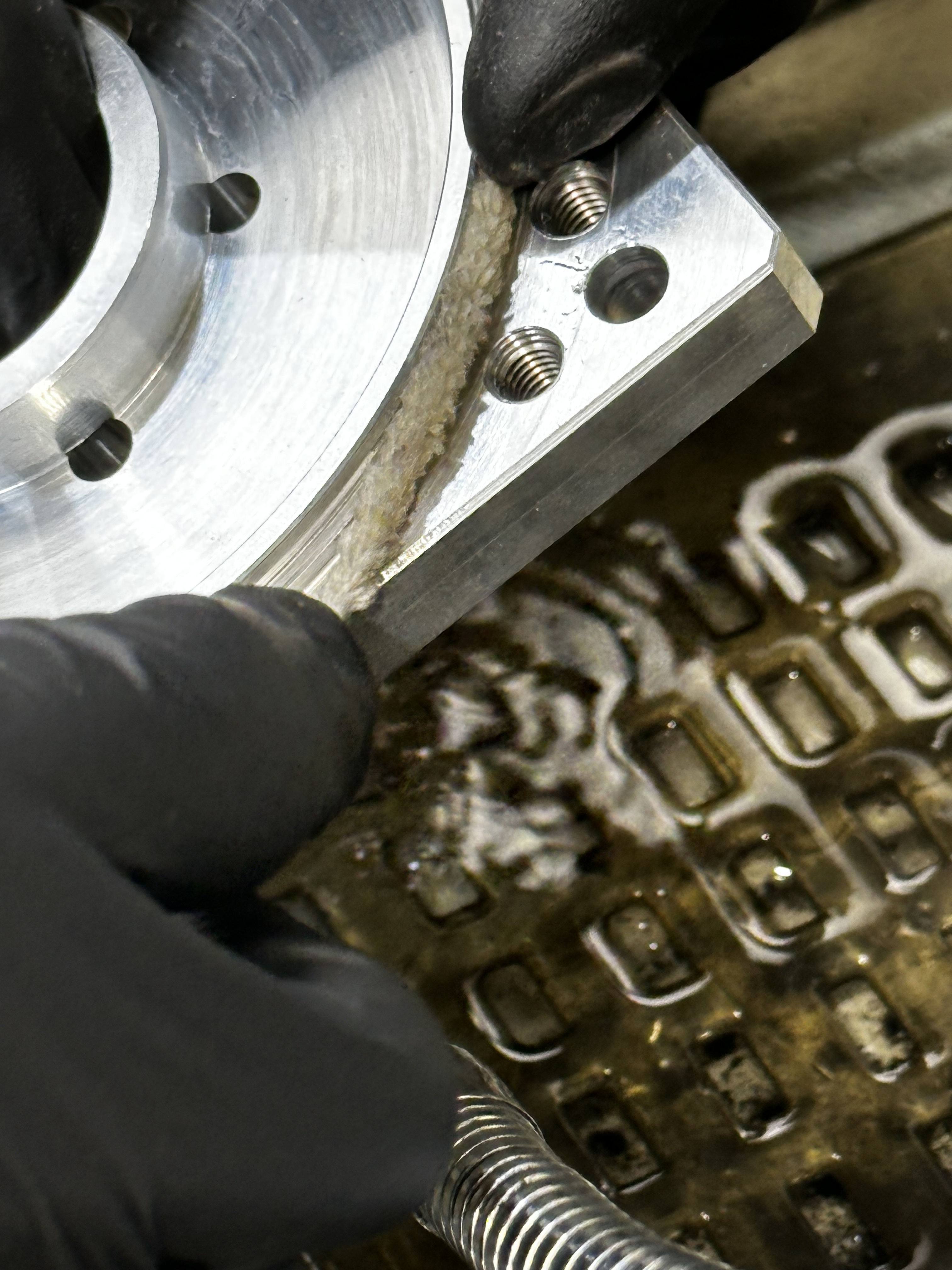
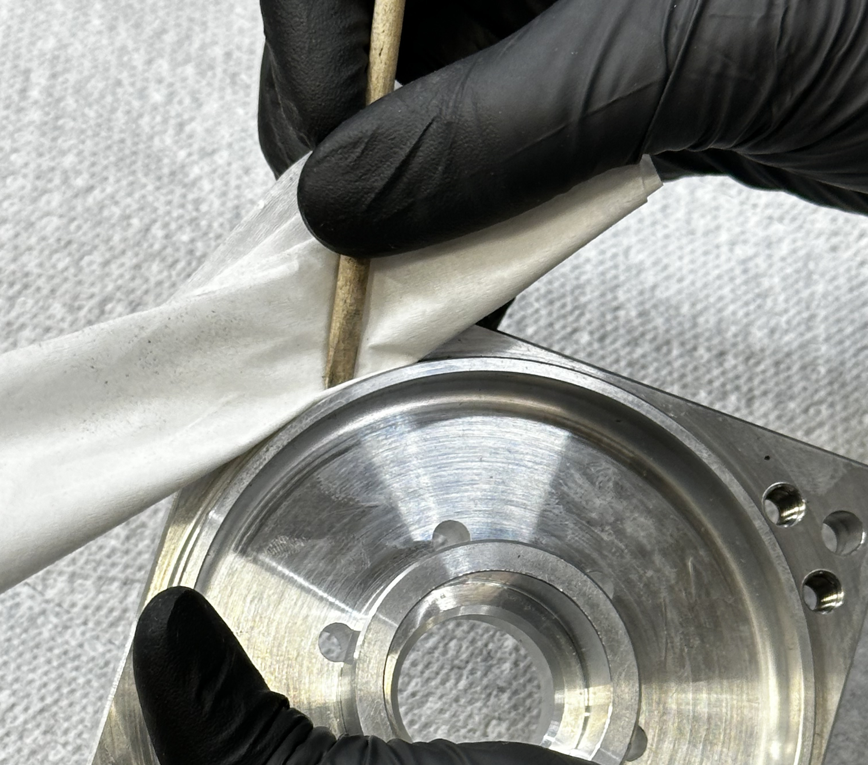
Using a kim wipe with alcohol on a wooden pick, clean the o-ring surface of any loose dirt or residual grease.
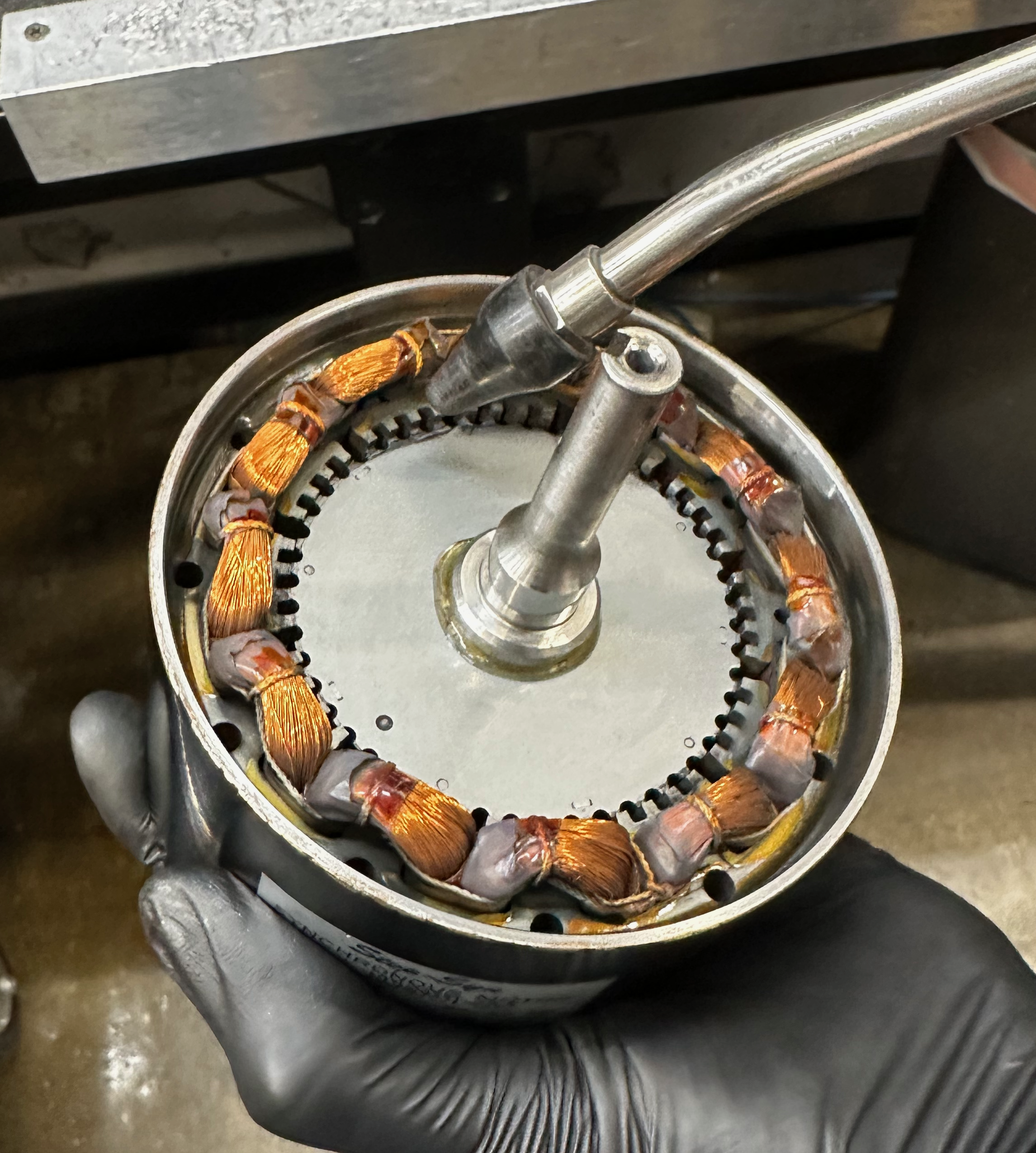
Using the scotch brite on the wooden pick, sand the o-ring surface.
Use compressed air, blow the sealing surface to clear any dust or debris.
Using a kim wipe with alcohol and wooden pick, clean the o-ring surface again.
Note
Flip over the motor and repeat the cleaning steps so that both sides fo the motor are cleaned.
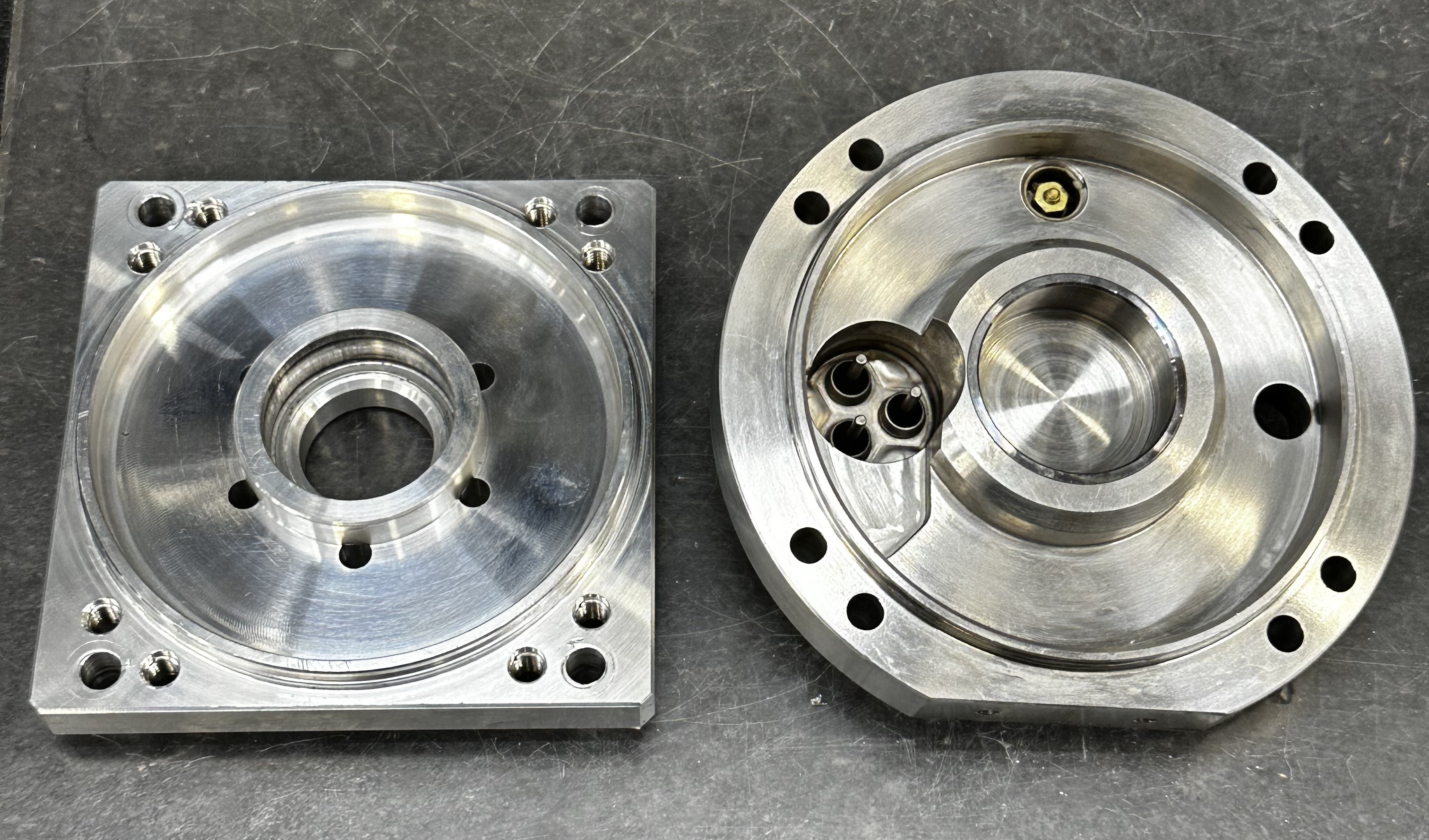
Preparing end plates
Obtain a new Motor crank plate and refurbished motor back plate.
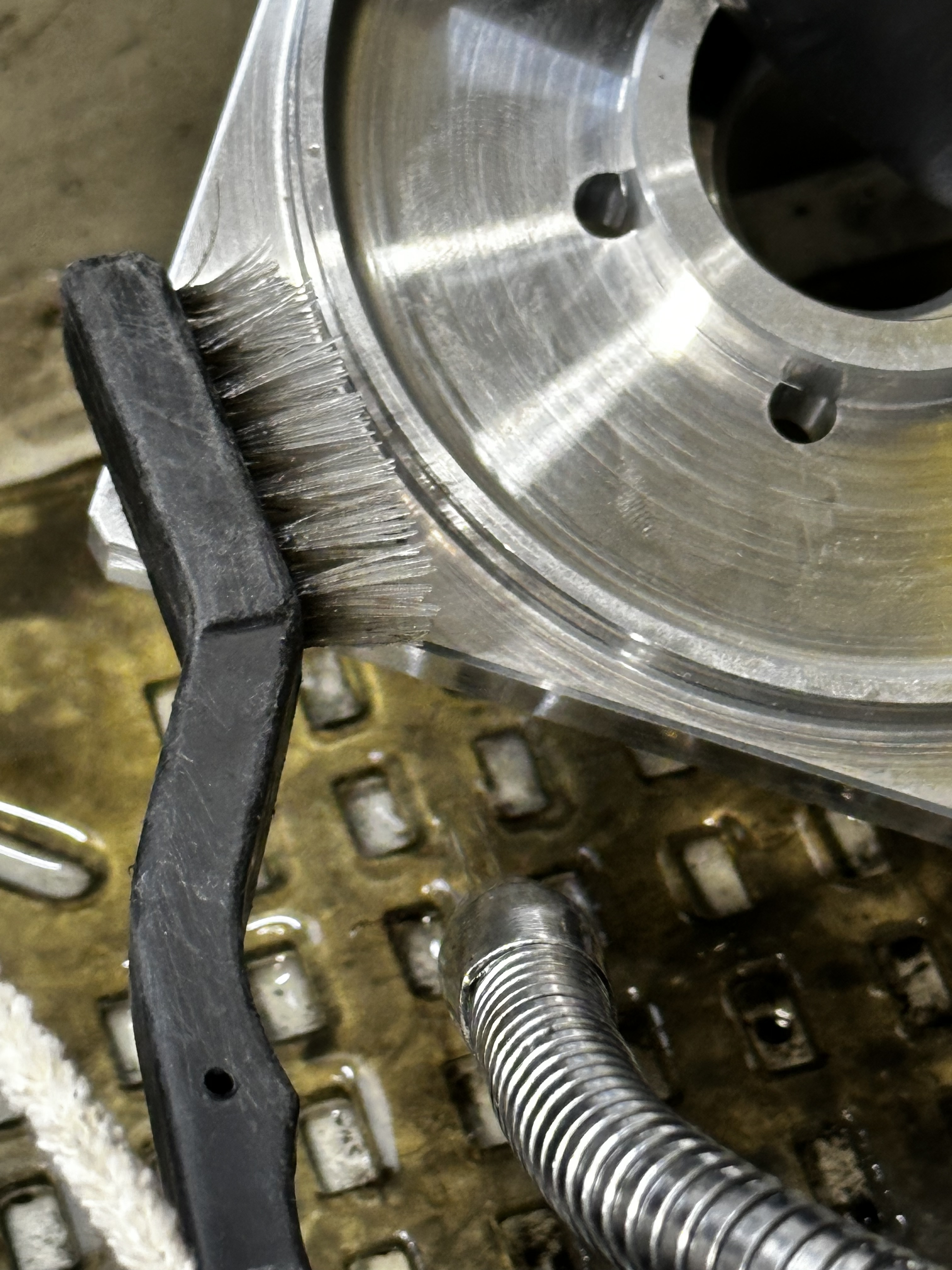
Clean any dirty surfaces and hole with a brushes.
Using a tube cleaning tool on the impact driver, polish the relief valve.
--
Clean the o-ring gland with brush, pipe cleaner, then kim wipe.
Blow off the alcohol from the end plates with compressed air until they are dry.
Assembling the Motor
O-ring Installation
Obtain 2 x -044 o-rings.
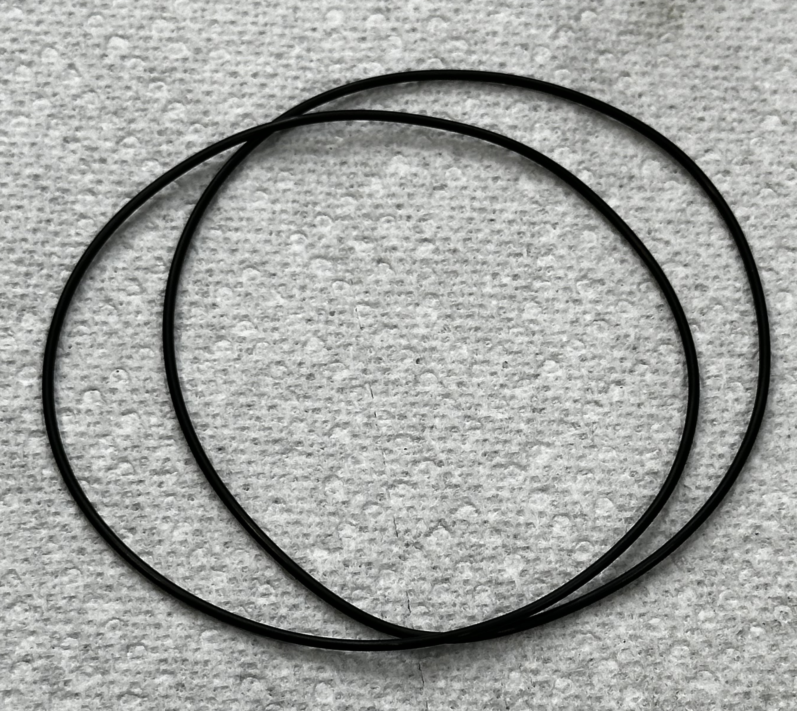
Apply an even thin coat of vacuum grease onto the o-ring and then install it into the o-ring grooves.
Note
Applying too much vacuum grease can cause leaks and damage to the o-ring from cutting.
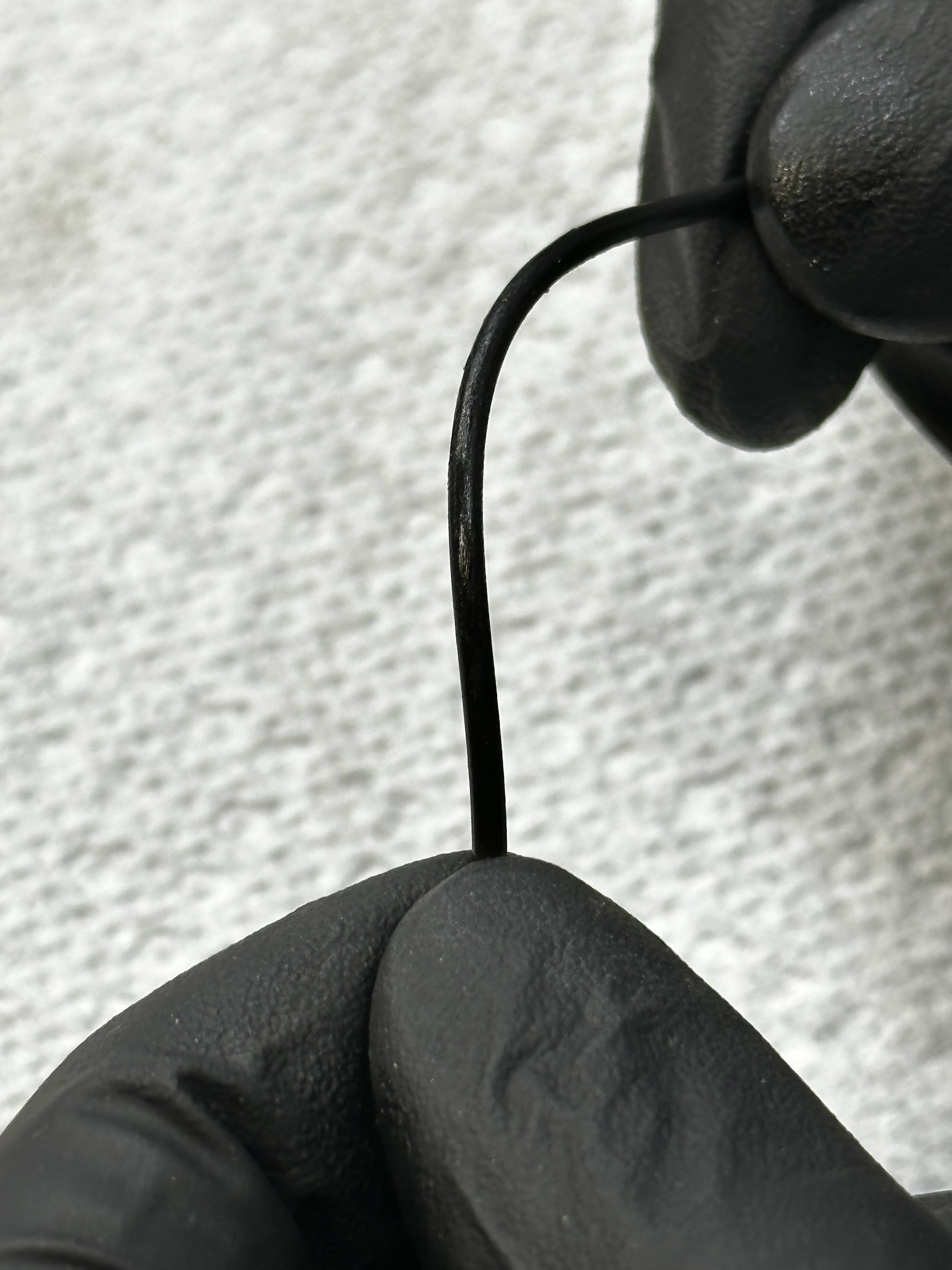
Pinch and release o-ring radially to ensure that they are not twisted.
The pinching motion lifts the o-ring out of the groove and allows the oring to untwist from rolling the o-ring into position. Do this in 2 - 3 locations around the motor.
End plates installation
Install 3 x spring washers into back plate bearing housing.
Connect the electrical wires onto the connectors in clockwise order - Black, White, Red. Take note of the length of each wire and their order.
The red should be the longest wire and installed on the furthest terminal.
Once they are all connected, push the back-plate onto the stator by hand until the o-ring is seated.
Place the motor crank shaft toward you with the flat portion of the back plate down on the bench. Install crank plate with the gas holes with three to the left and right.
Squeeze the crank plate with your hands until the o-ring is seated.
Using a star pattern, lightly tighten the 8 x M6 motor bolts with impact driver.
Ensure the crank plate and back plate flat section are true. Tap with a mallet to settle the plates.
Use the torque wrench in a star pattern to tighten the motor bolts.
Be sure the torque wrench is set to (VALUE IN INCH POUNDS).
Test the motor rotor has smooth rotation by turning the crank by hand.
Warning
Keep clear of the receptacle pins during this process. The turning action will produce voltage and shock you.
Drive Receptacle Installation
To install the motor drive connector fasten 1 x JIS # 2 screw on connector ground wire ring terminal.
Install triangular connector by hand.
Fasten the receptacle down with 4 x JIS # 2 screws on the housing.
Quality Check the rebuild
Begin by verifying the electrical connections of the motor. To do this repeat the steps in the Electrical Pre-Check.
Resistance A to Ground = O.L. A-B, A-C, A-D = 242-260 and ± 2 ohms between each leg.
| PINS | A | B | C | gnd |
|---|---|---|---|---|
| A | NA | 242-260 | 242-260 | OL |
| B | 242-260 | NA | 242-260 | OL |
| C | 242-260 | 242-260 | NA | OL |
| gnd | OL | OL | OL | NA |
Perform the Torque Test steps and record the results.
1. Vibration = Low, Med, High

2. Torque >= 600 oz in
Obtain a new -018 o-ring, apply small amount of grease and install it on the aeroquip bung.
--
Obtain a new aeroquip and green heat shrink.
Install the aeroquip using the 1 ⅛” deep well socket and the impact driver.
Use the heat gun to shrink the green tubing on the back of the aeroquip.
Crank Installation
Install the new keystock into the keyway with the watchmakers hammer.
Warning
The shaft must be supported by the support fixture during the tapping process or the shaft will bend.
Use the calibrated (FIVE OR SIX MILLIMETER SPACER) to install the crank the proper distance from the front-plate.
Slide the crank onto the shaft.
Make sure there is no gap between the crank an the spacer but don't press so hard the spacer cannot be removed.
Tighten the set screw with 2.5mm L-key
Complete the motor repair form.
Place the motor in the ready-to-use area.
Appendix
-
For motors that do not spin freely and or have low torque after repair…
-
Remove end plates.
-
Check Bearing housing I.D. to be less than or equal to .0005”
-
Check -44 o-ring groove base to be 102.16-102.20 mm.
-
Check bearings for ease of spinning, replace as necessary.
-
Reassemble and retest.
-
If still not free spinning remove rotor and inspect for lamination's separation or debris between rotor and stator.
-
Remove debris or replace rotor or stator depending on source of interference.
-
Re-assemble motor as per directions above and set for Re-Mag.
-
For motors that are shorted or have bad windings…
-
Remove rotor, inspect lamination.
-
If lamination's separated, record tag and set aside for future repair.
-
Place tag with electrical information on stator and bag for future re-winding.
-
Obtain stator with good Ohms and re-use (if in good condition) rotor or obtain good rotor from stock.
-
Re-assemble motor as per directions above and set for Re-Mag.