ZM-NANO-PANEL-MN Assembly
This work instruction outlines the assembly of the panel assembly for the Zeromonitor Nano. This is the base configuration designed to work with Siemens magnets.
Materials
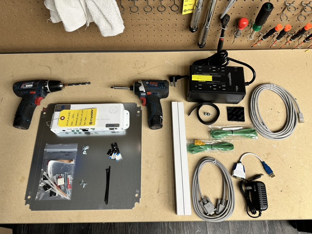
The materials required are as imaged below.
Note
Please verify with the most current version of the bill of materials that all the components are present.
Mounting Fixture
The mounting fixture for which all the components mount too is made up of the two pine boards and a galvanized steel plate. They are fastened into place with wood screws.
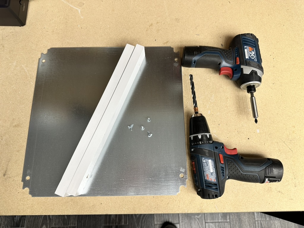
Predrilling Mounting Holes
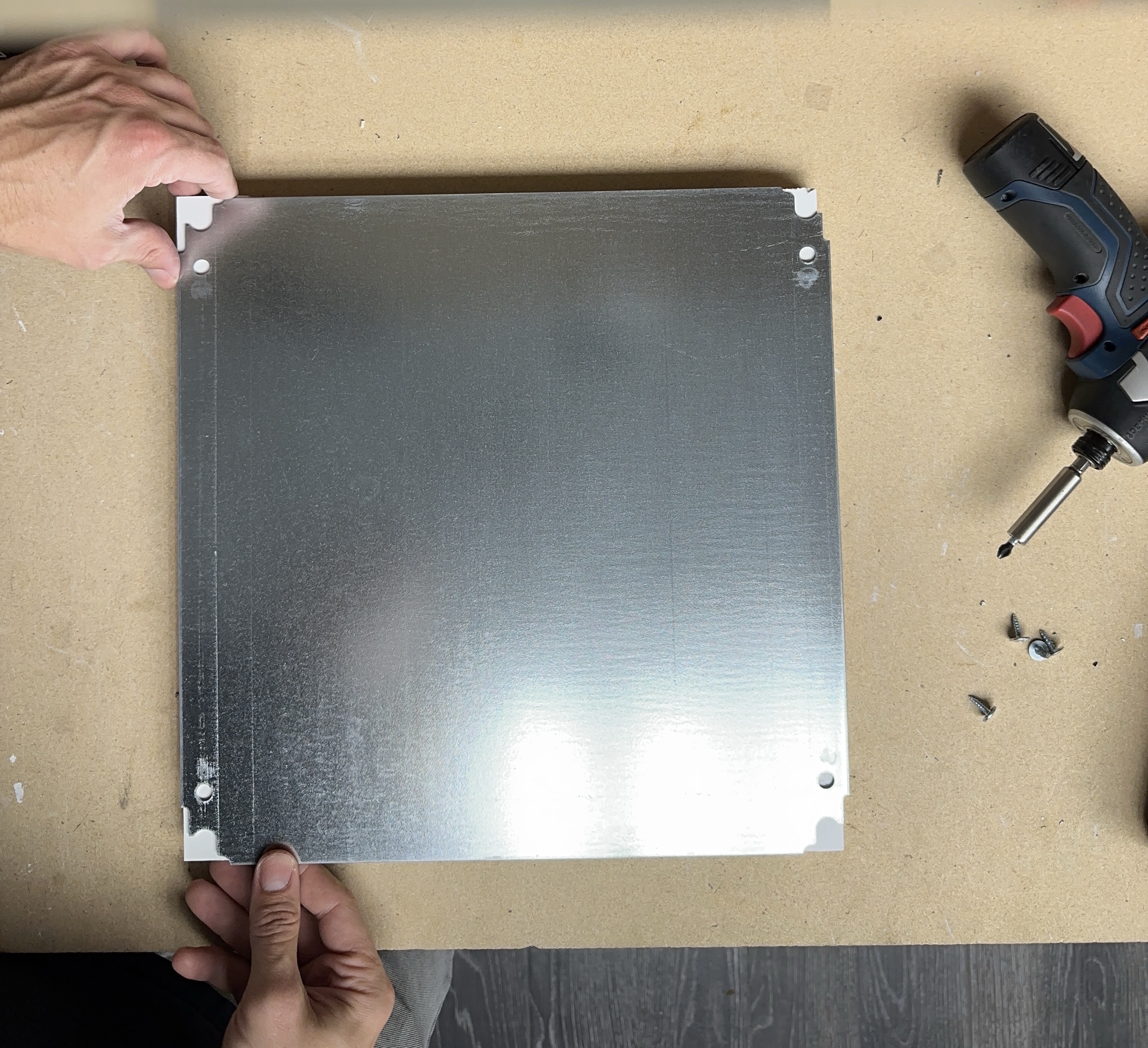
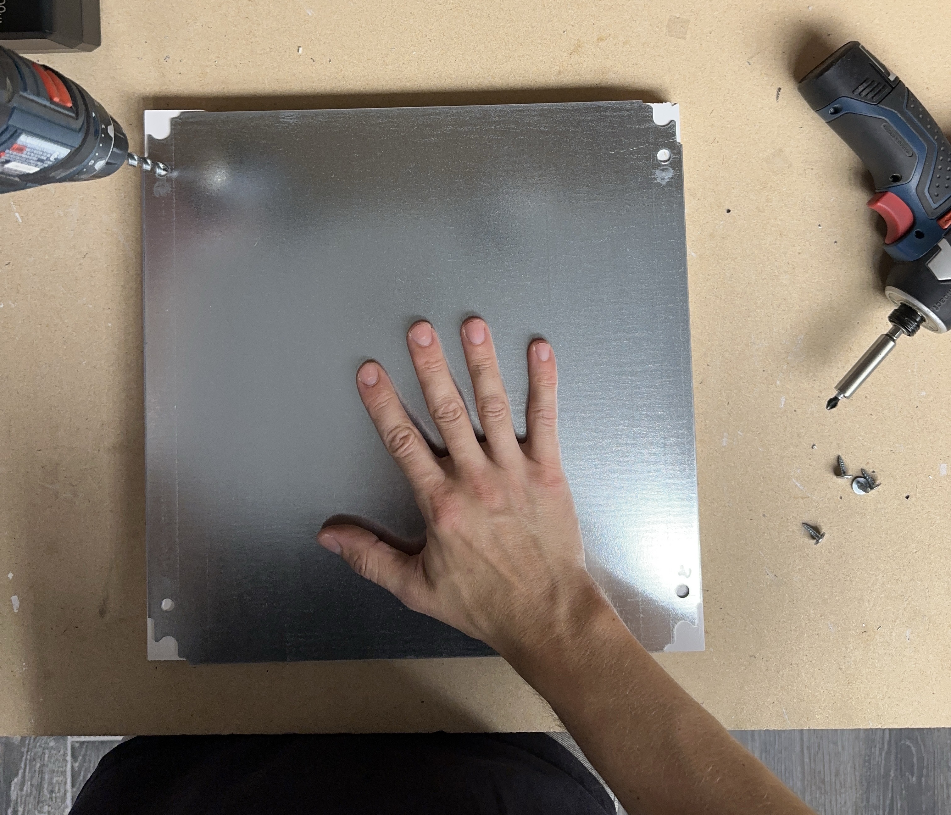
The panel requires through holes in order for the fixture to be mounted to the wall on site. Begin by squaring the boards with the edges of the galvanized plate.
Use a centering punch to mark the center of the holes for the location of the through holes.
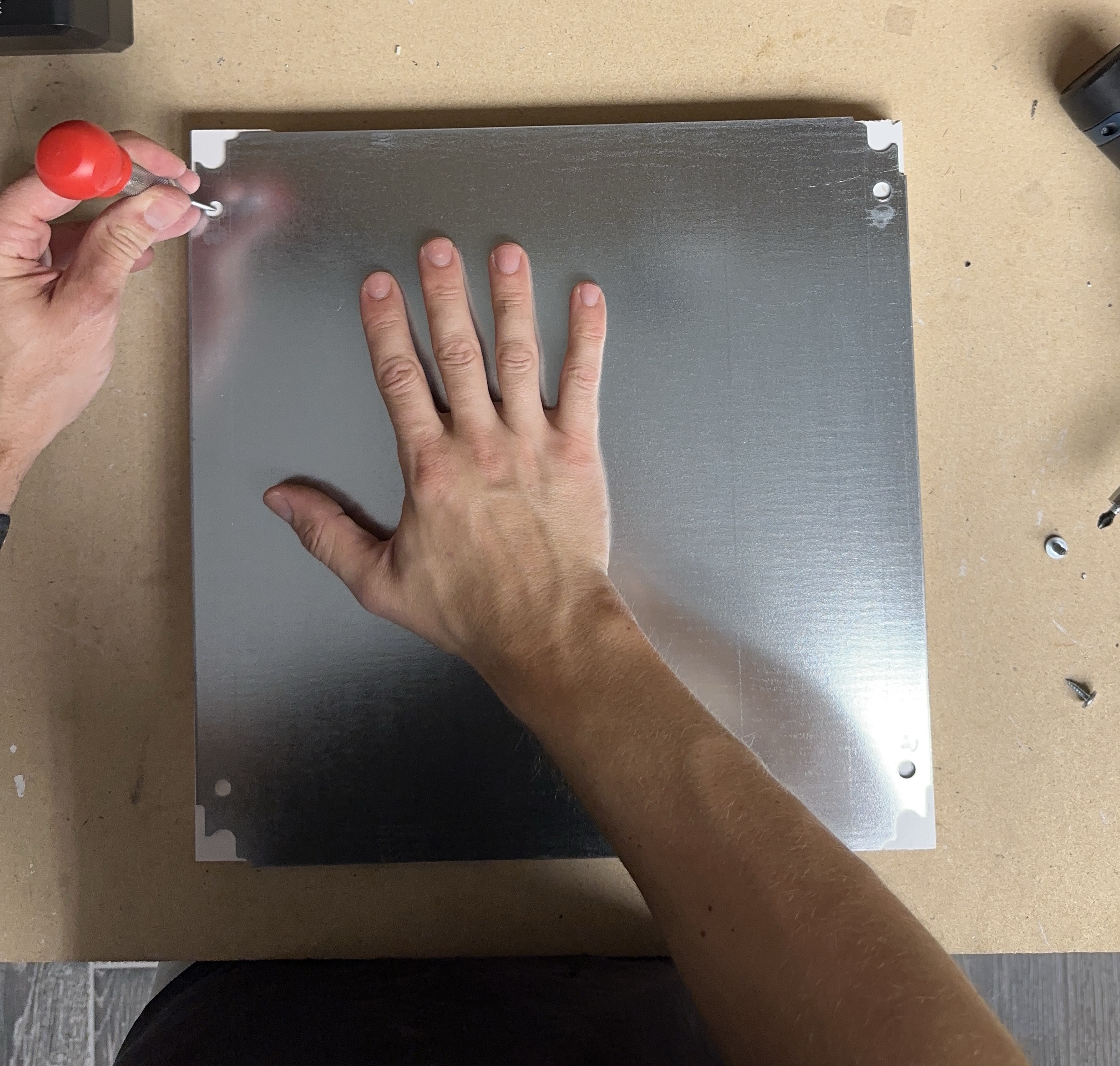
Warning
Do not drill the through holes into the bench. The below image is for reference only. Perform the through hole drilling in a controlled environment.
Drill the through holes using a 7mm drill bit.
Fastening Boards to the Plate
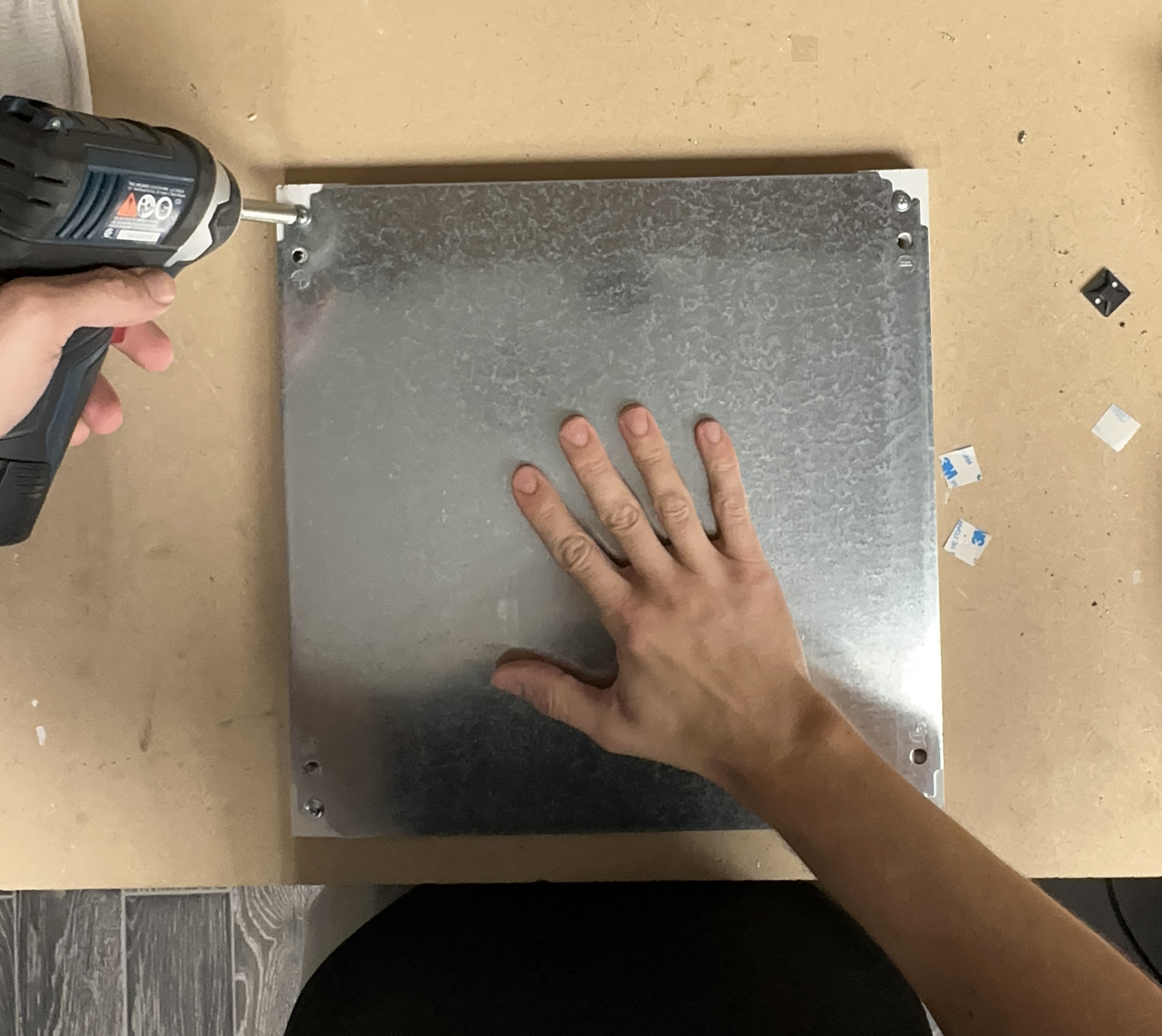
Making sure that the boards are square with the edges of the plate, use the wood screws to fasten down the plate to the boards. The screw must be driven down close enough to the plate in order for the head to pickup the edge but not so close as to move the boards out of square.

Fastening UPS to the Plate
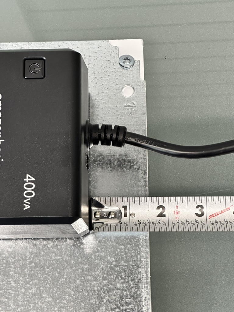
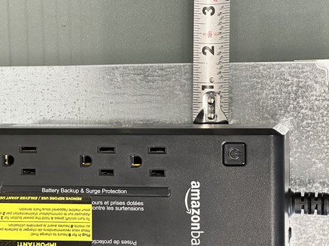
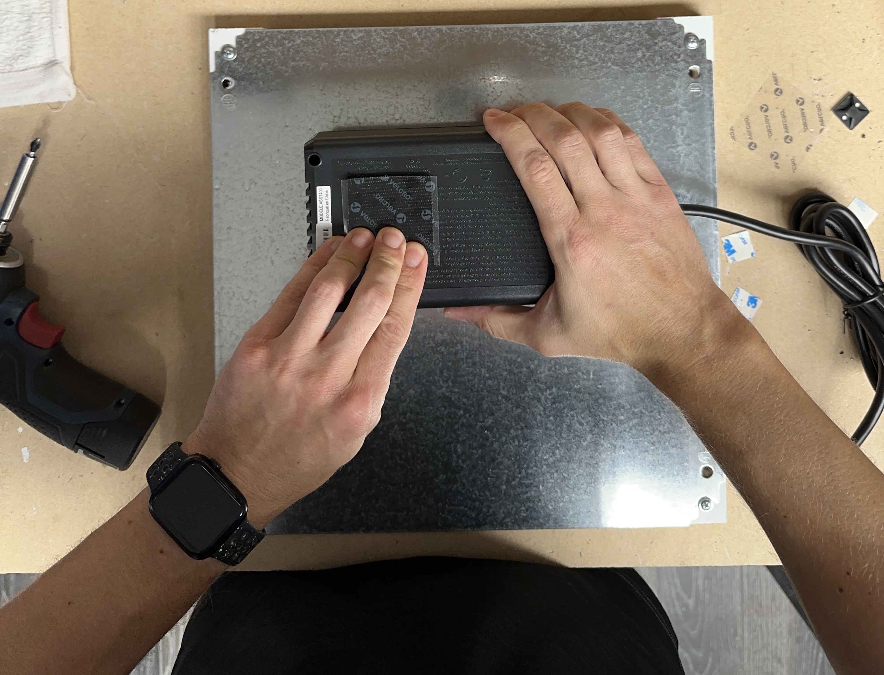
The ups is mounted to the plate using adhesive backed velcro and a nylon strap. The UPS is positioned in the top right corner of the plate.
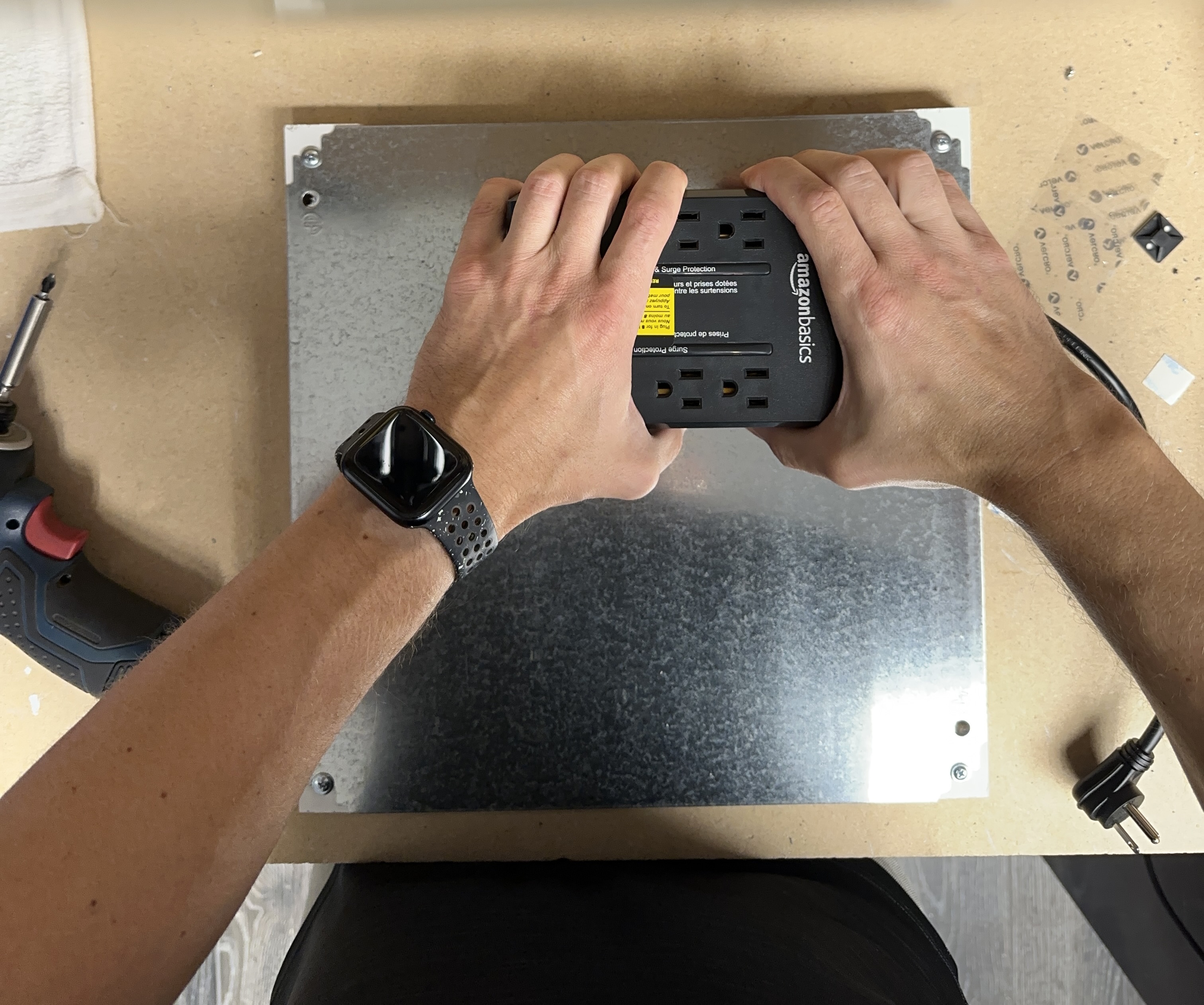
Positioning the UPS
Position the UPS 1 ½ inches from the top and from the right side of the plate.
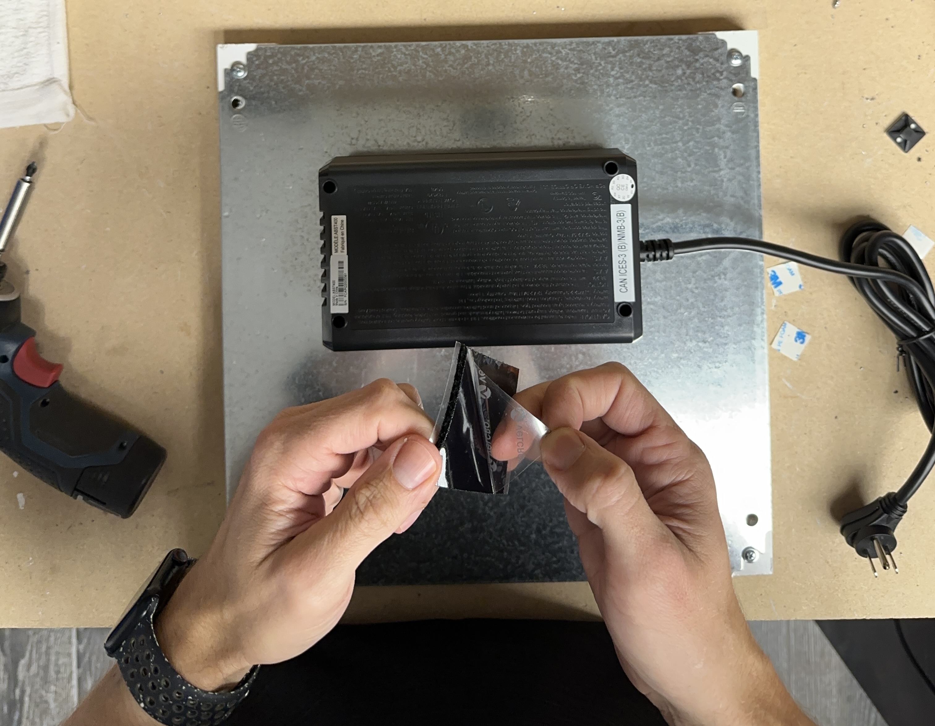
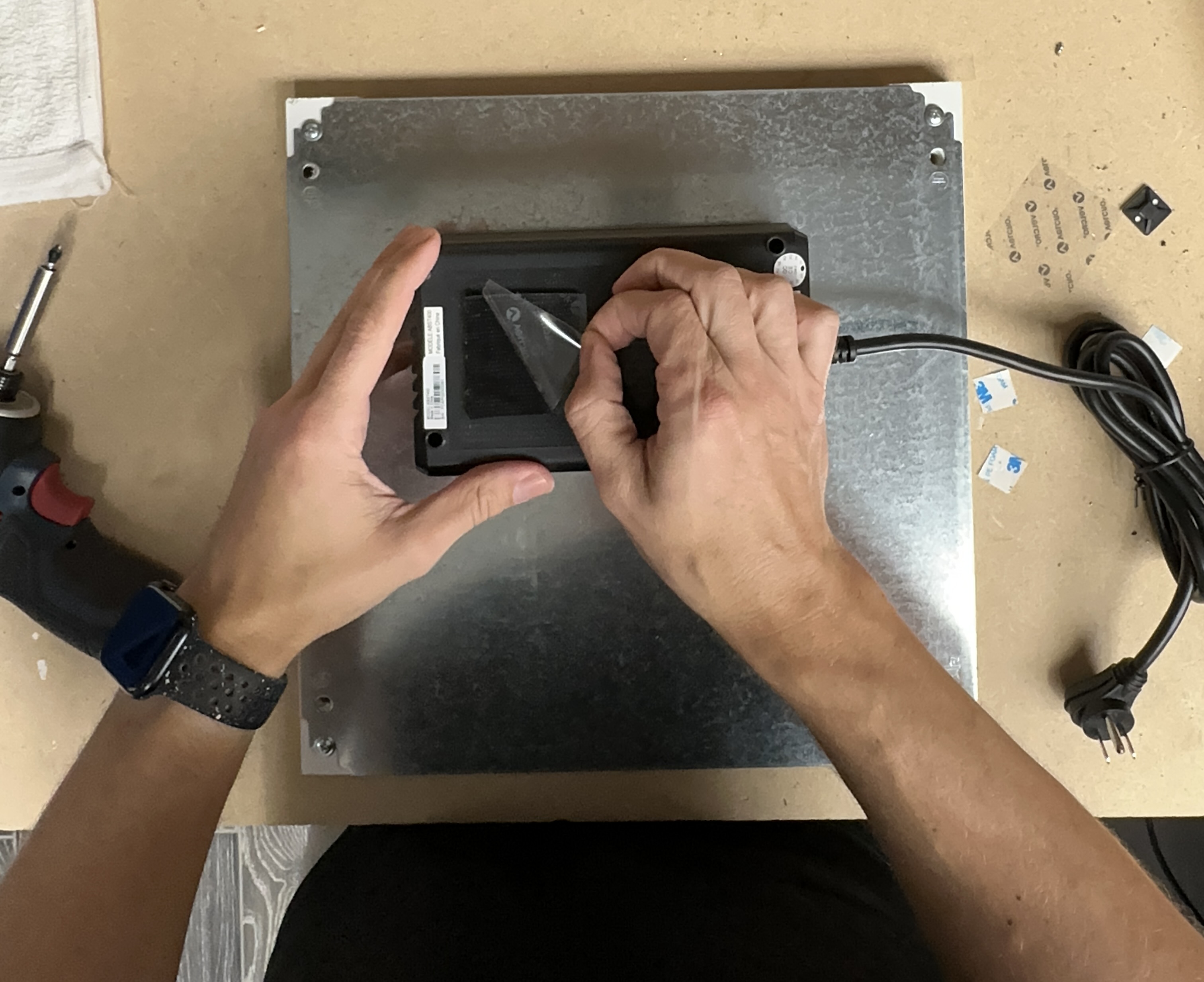
Adhering the UPS
Marking the Strap Location
Use the center punch to mark the location for the through holes. Position the marks so that the strap runs between the receptacle and the power button.
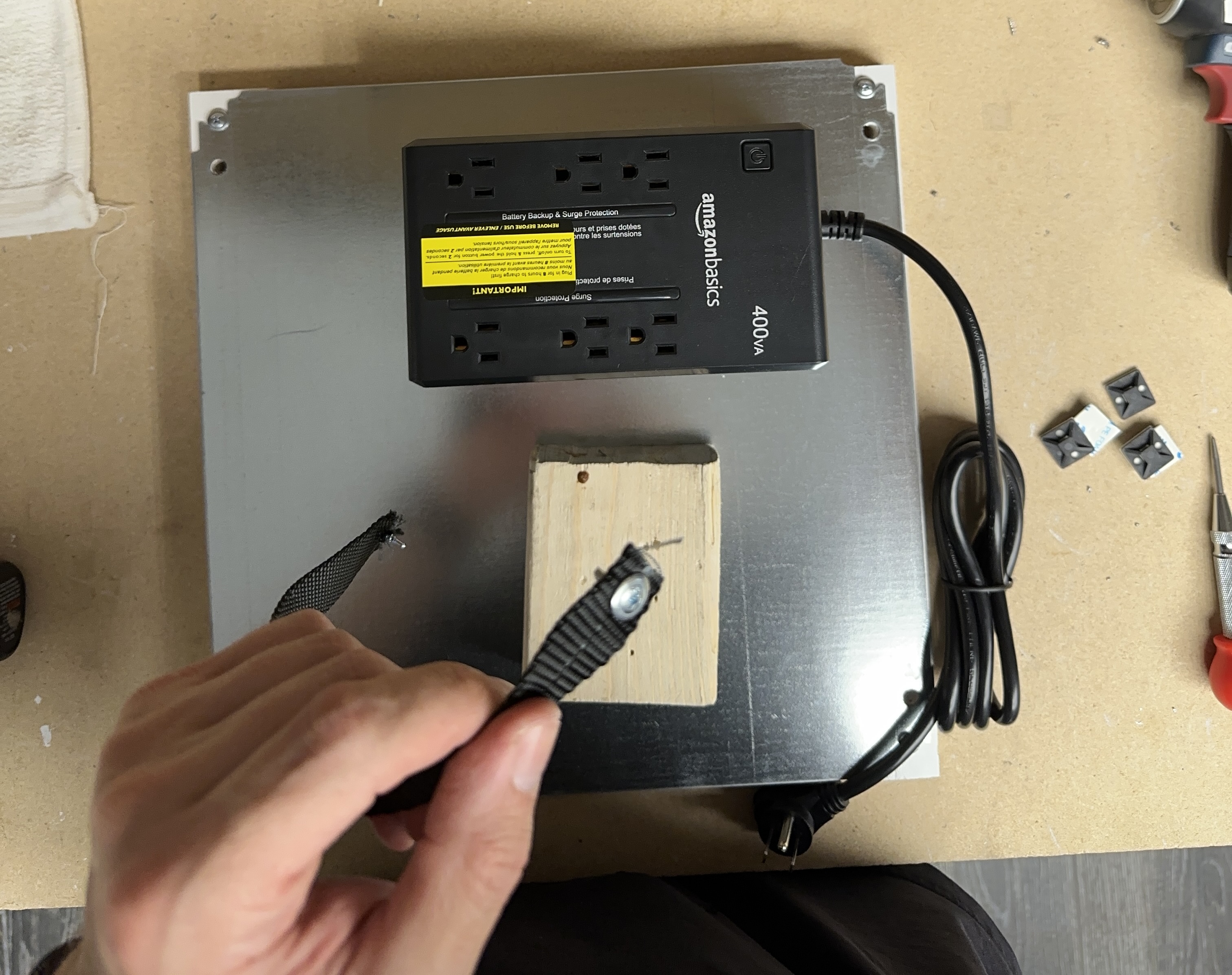
Prepping the Strap
Using the center punch, push a hole through the nylon strap about ½ inch from the end and force the punch through to widen the hole. Repeat on the other side of the strap.
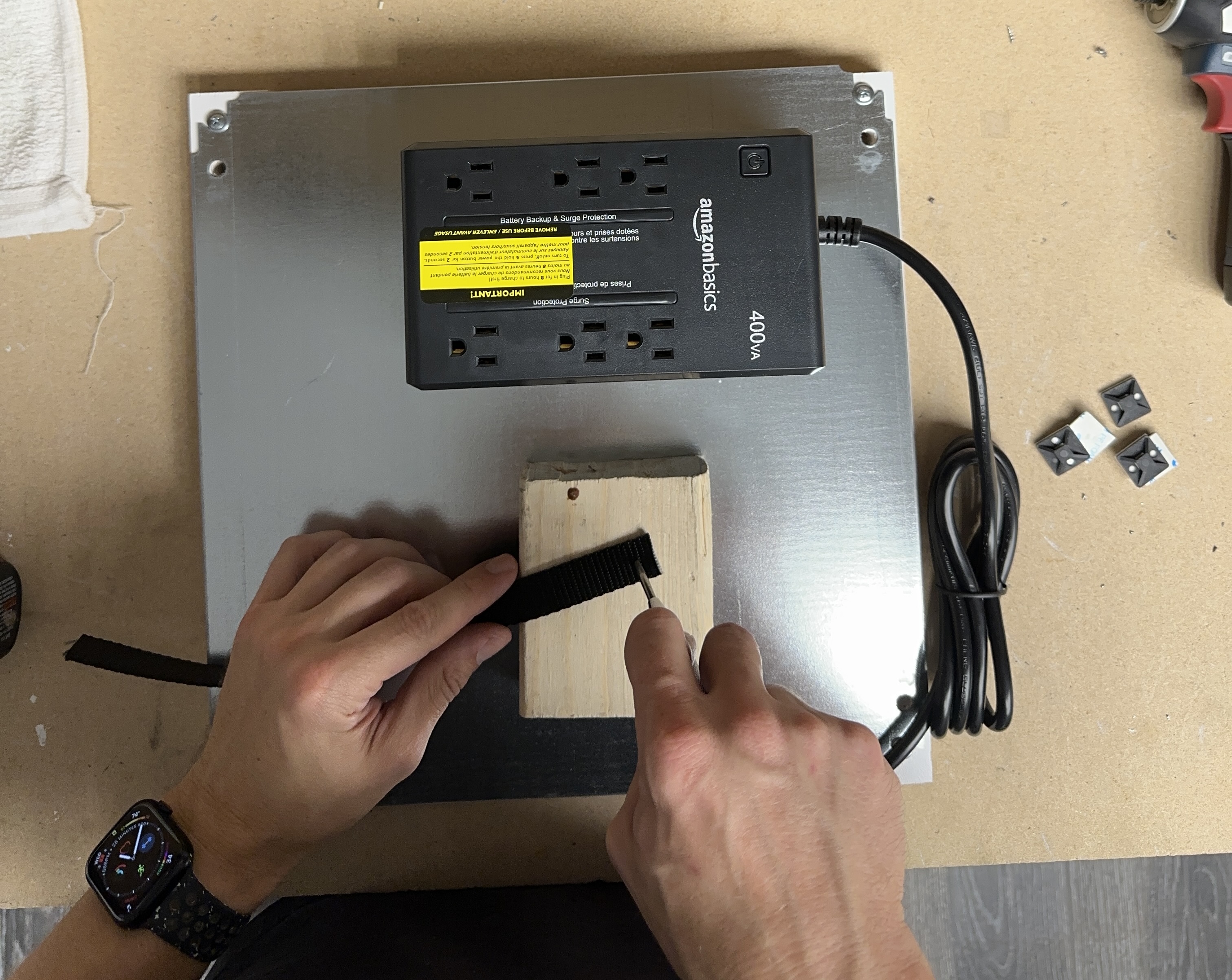
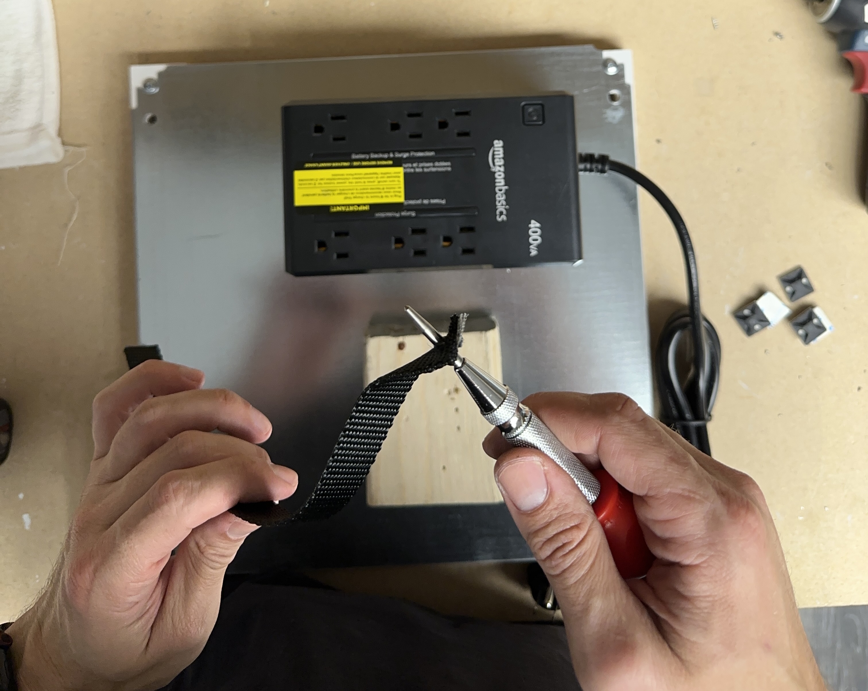
Run the self tapping screw through the holes in the nylon strap.
Tip
Use a hand driver to thread the screw through the strap.
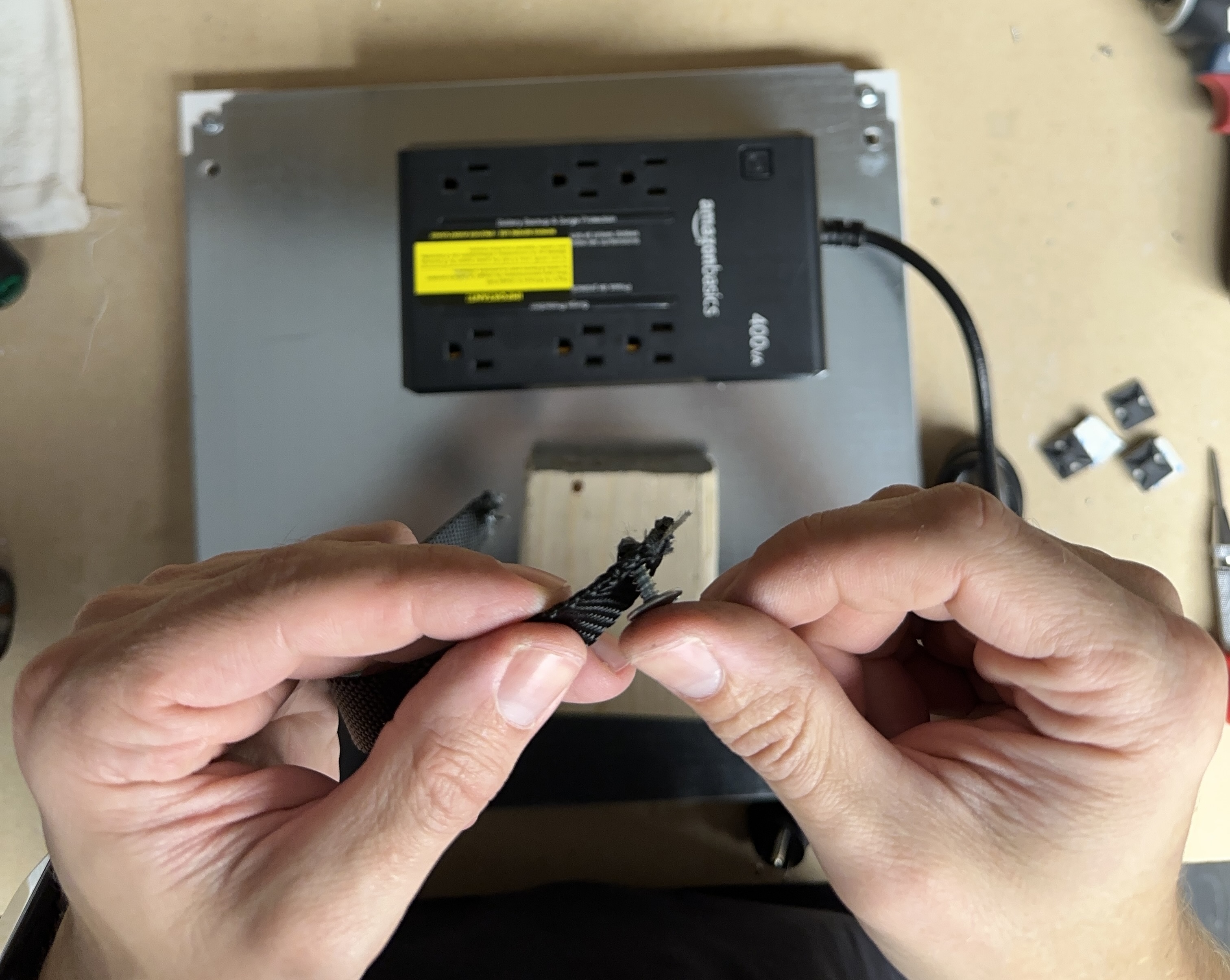
Pre-Drilling the Strap Holes
Pre-drill the holes for the screws using a 3.5mm or 4.0mm drill bit.
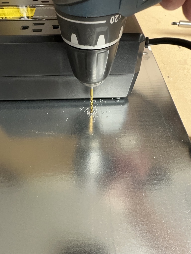
Tip
Using a self tapping screw to pre-drill the hole makes a perfect hole.
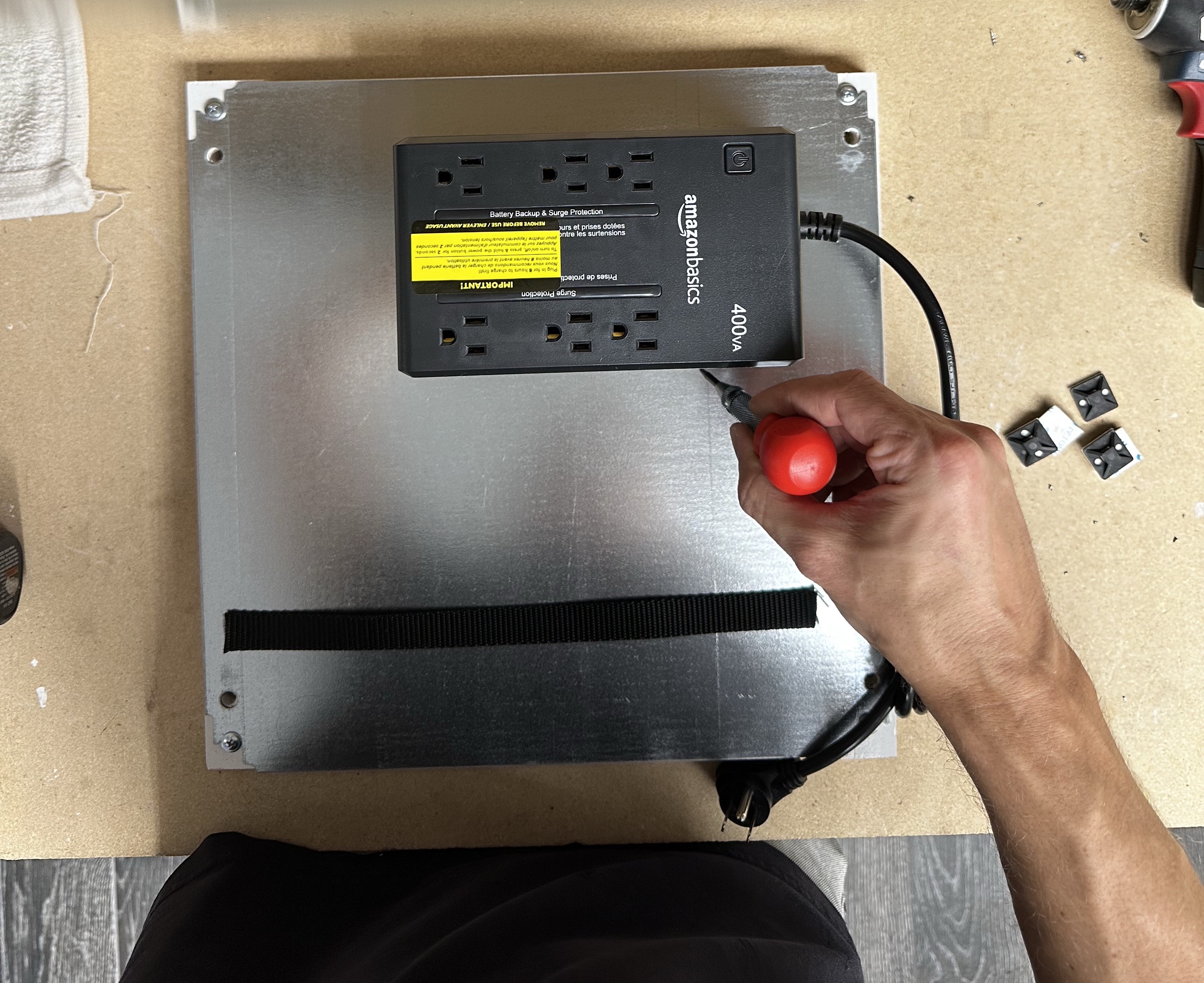
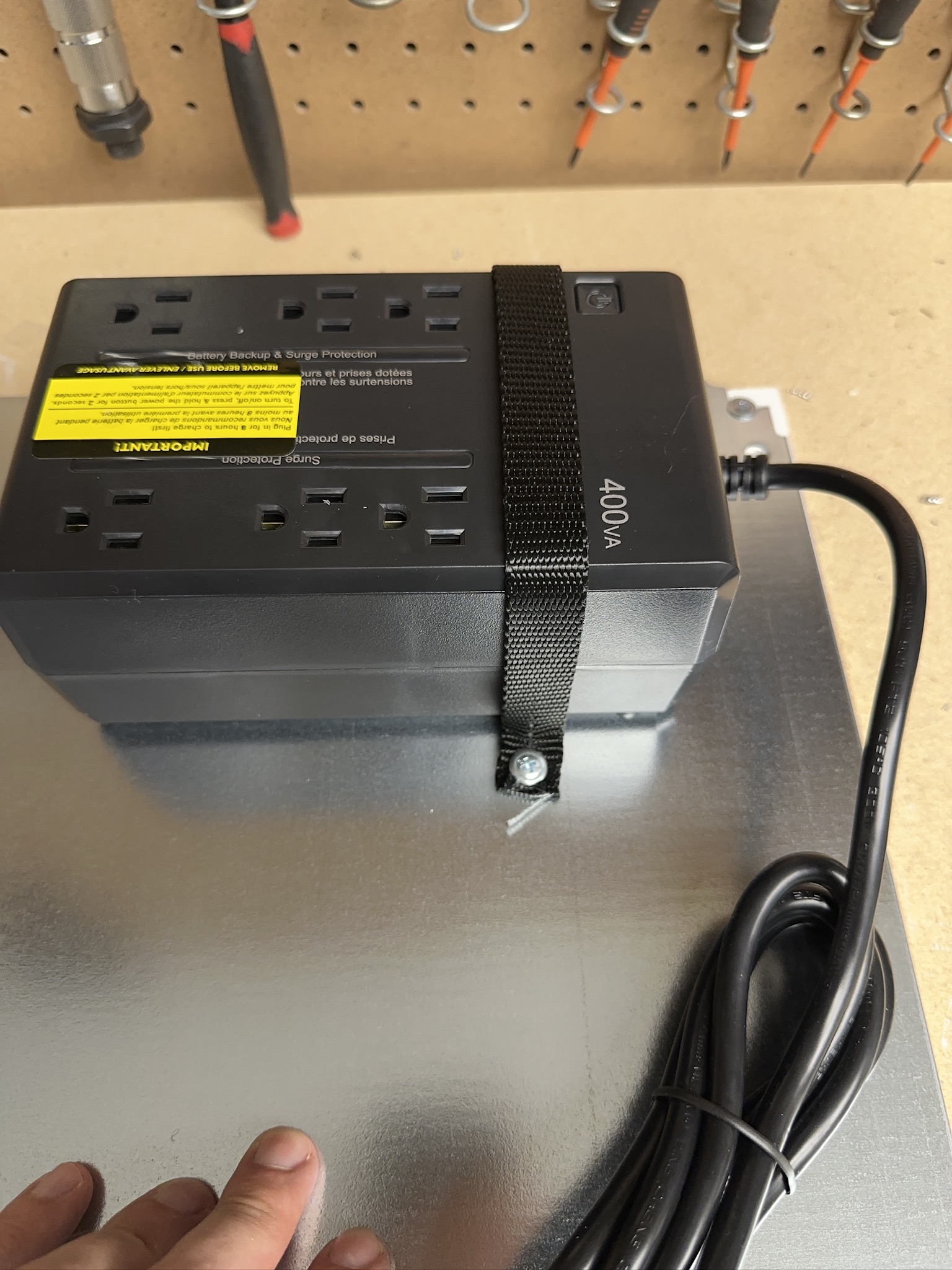
Fasten Down the UPS
Warning
Use a hand driver for this process. Using a powered driver will bind to the strap and wrap up in the drill.
Fasten the strap across the UPS to the plate.
Covering Receptacles
The remote monitor requires power conditioning as well as a temporary backup. To make sure that the monitor is plugged into the correct receptacle and that no other devices are plugged into the UPS that might draw power during an outage.
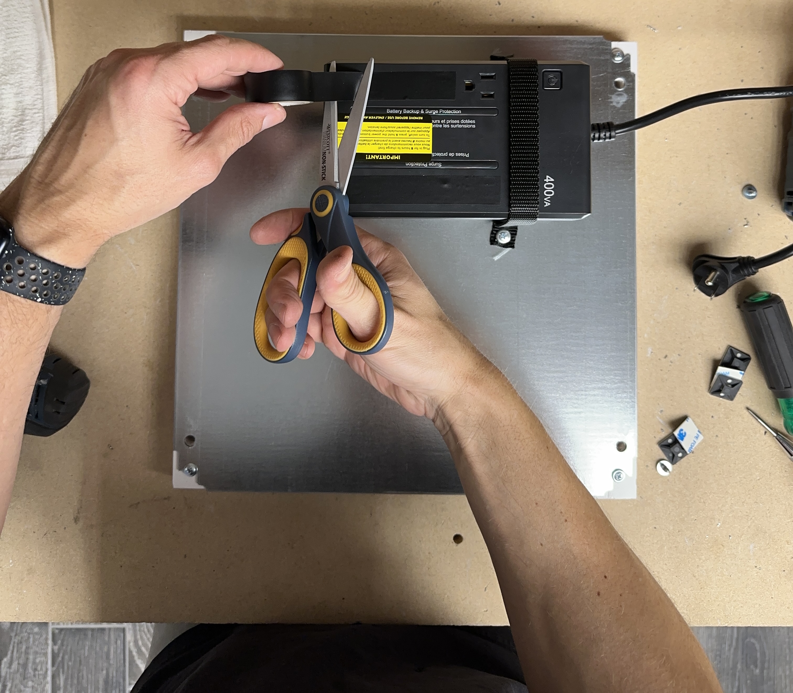
Using a piece of electrical tape cover the bottom surge protection receptacles.
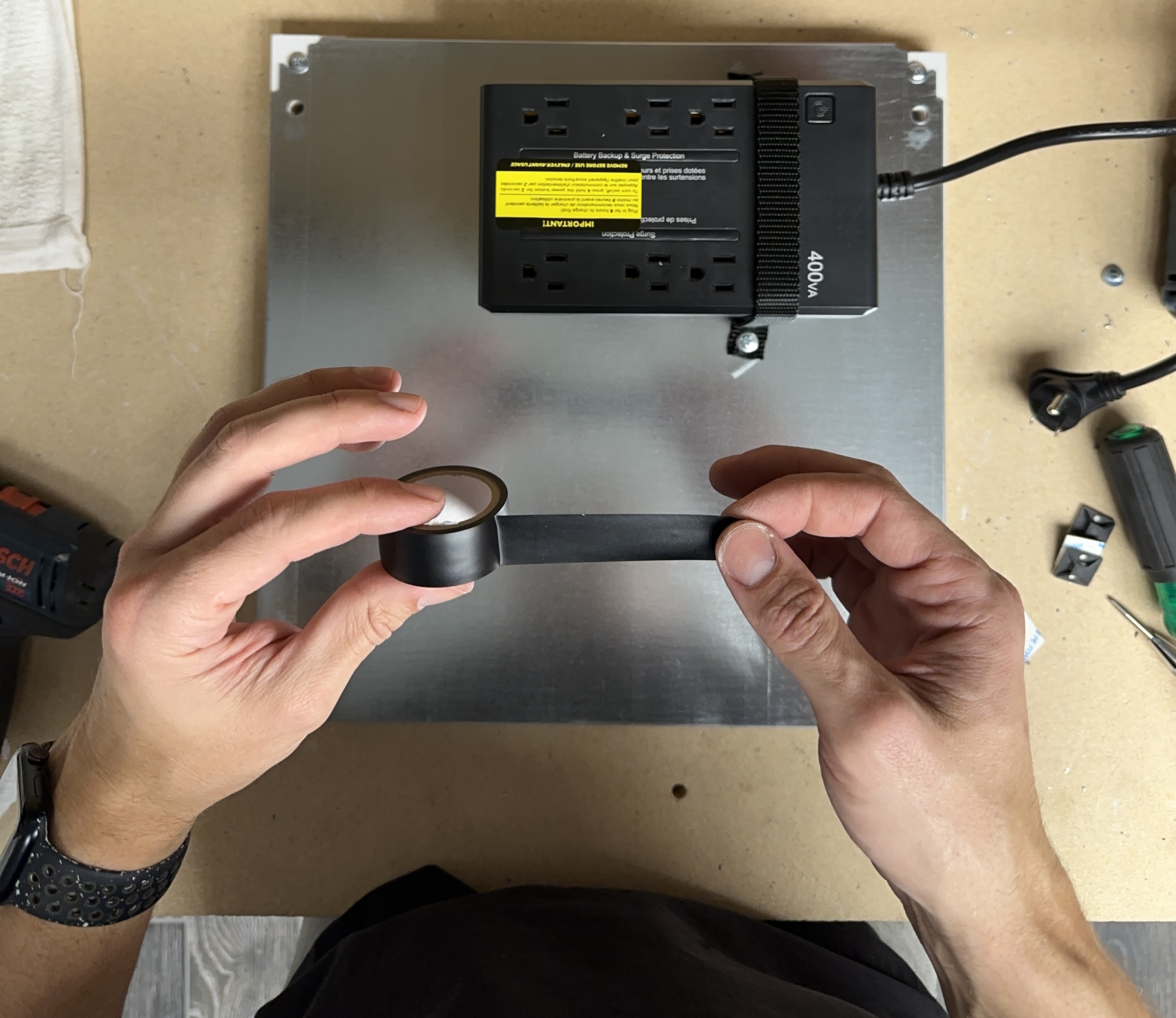
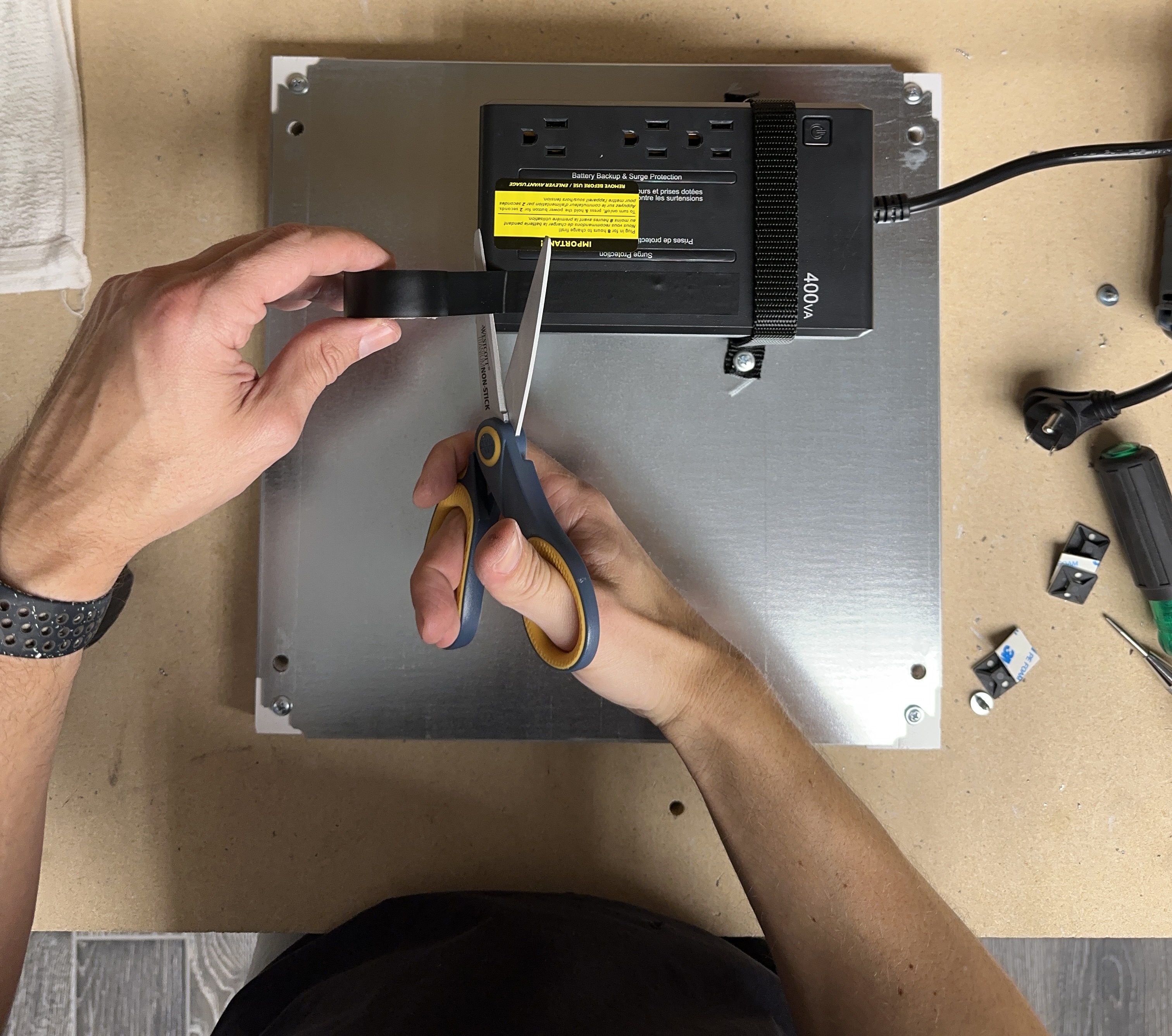
Repeat the same process for the top receptacle but leave one receptacle open for the power adapter to the remote monitor.
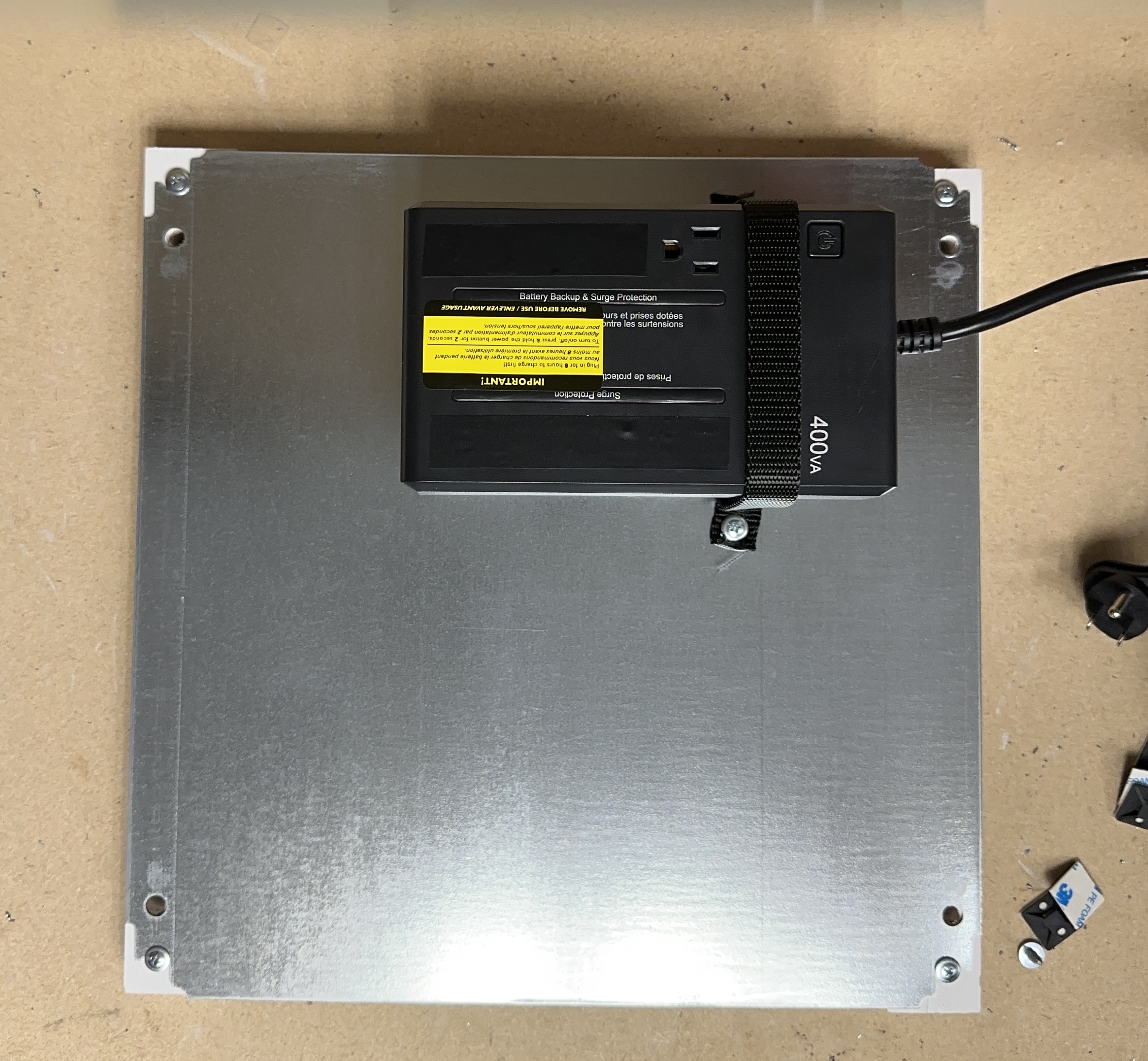
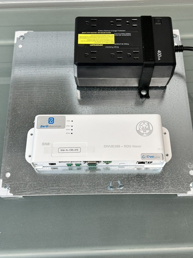
Final UPS Configuration
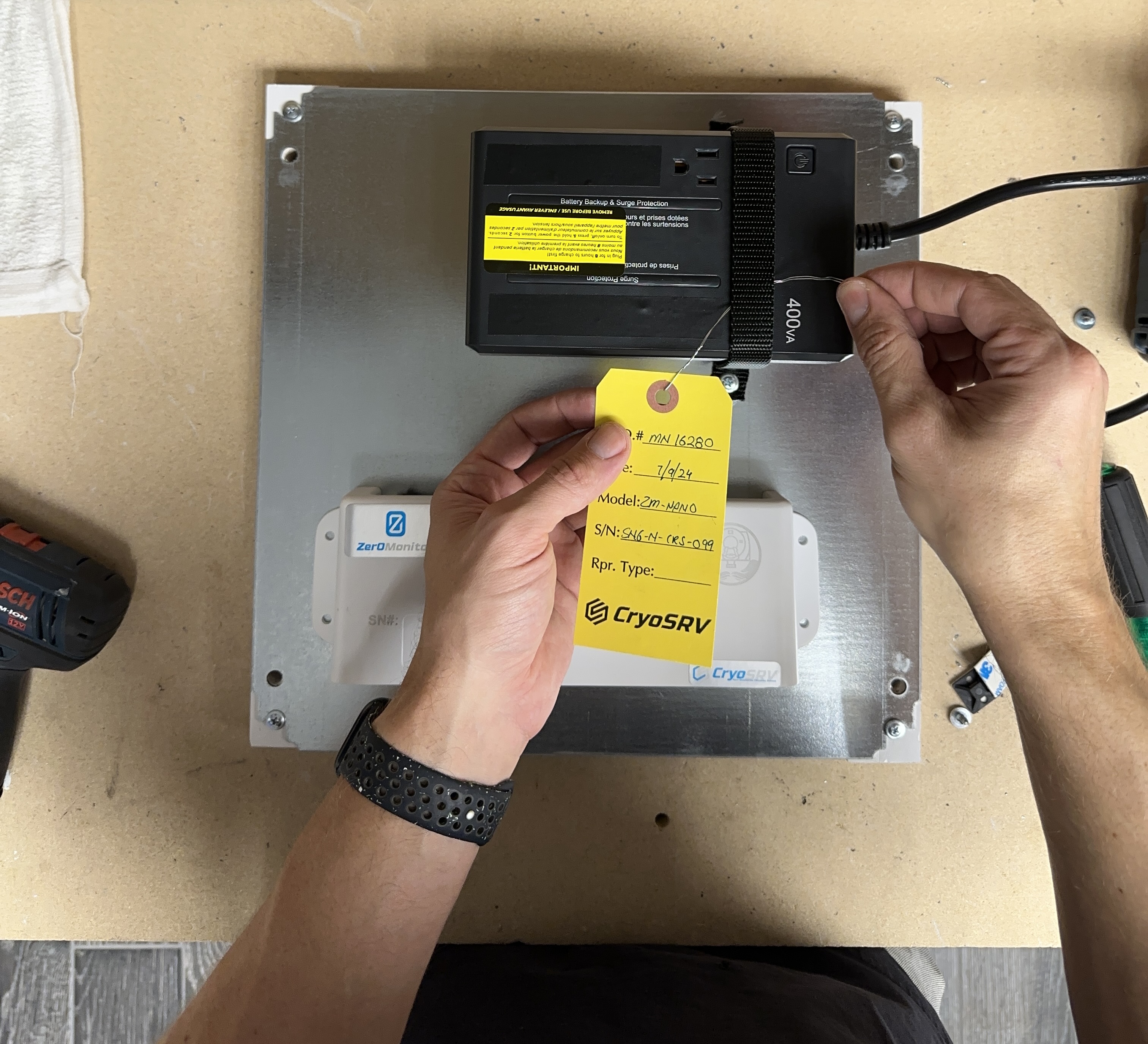
Mounting the Nano Monitor
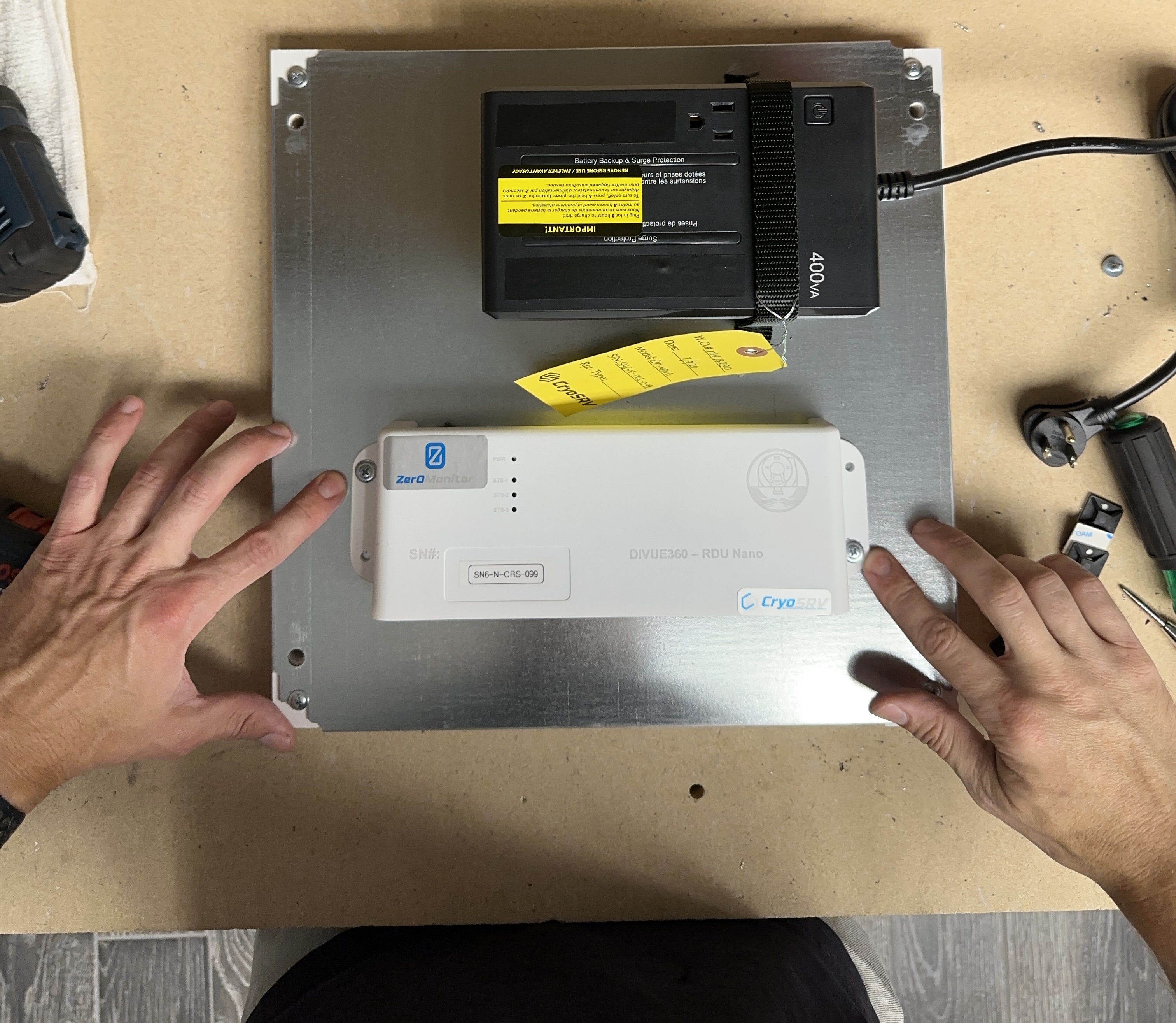
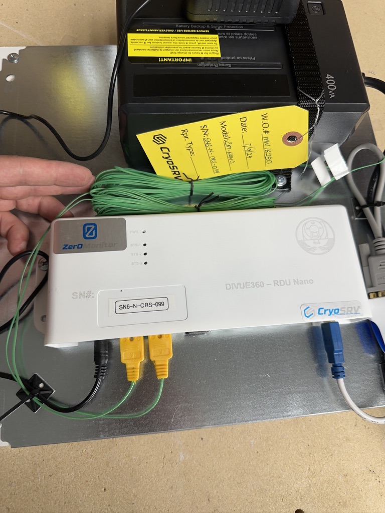
Prior to mounting the remote monitor, remove the work order tag and wire tie it to the UPS.
Positioning the Nano Monitor
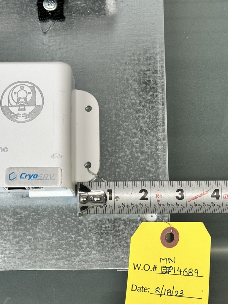
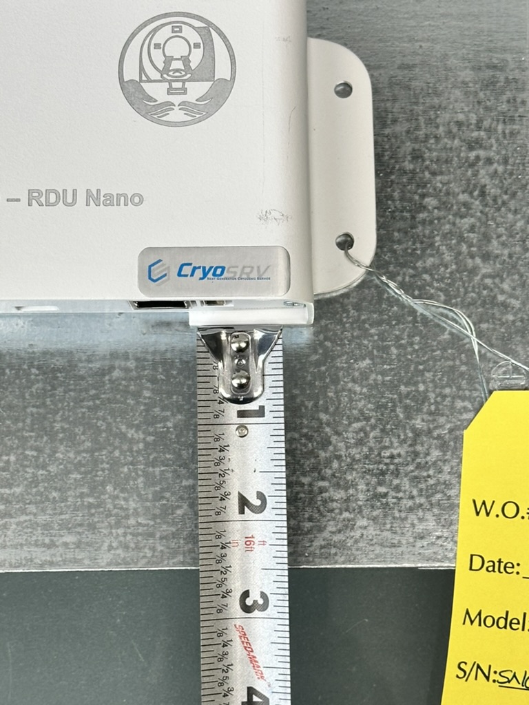
Measure the remote monitor about 3 inches from the right of the plate and 2 ½ inches from the bottom of the plate.
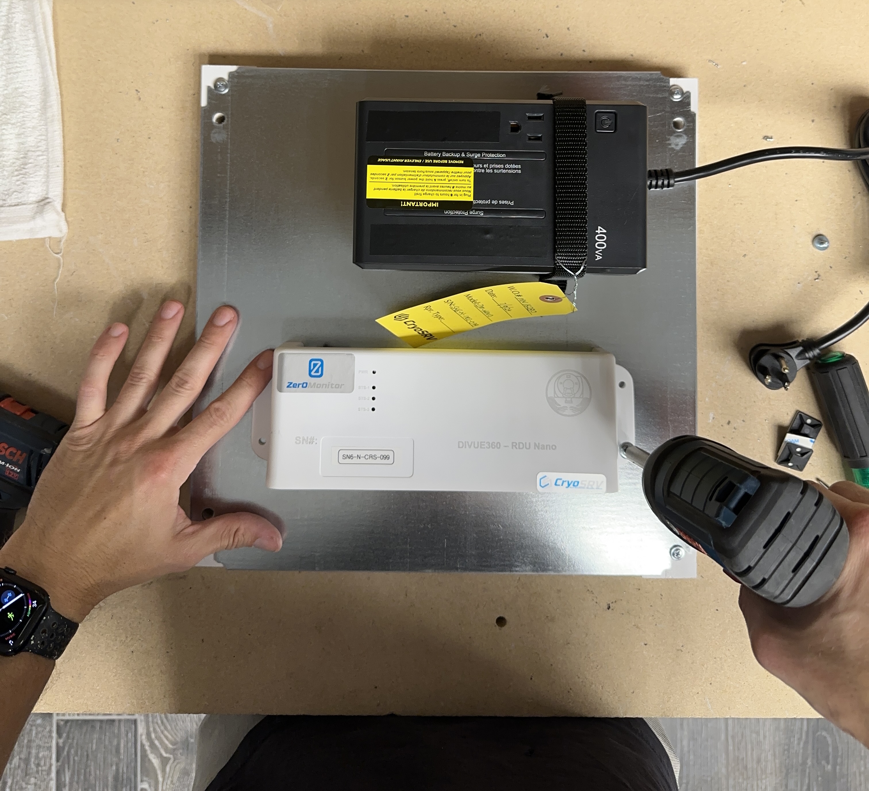
Fasten Down the Nano Monitor
Use self tapping screws to fasten down the remote monitor.
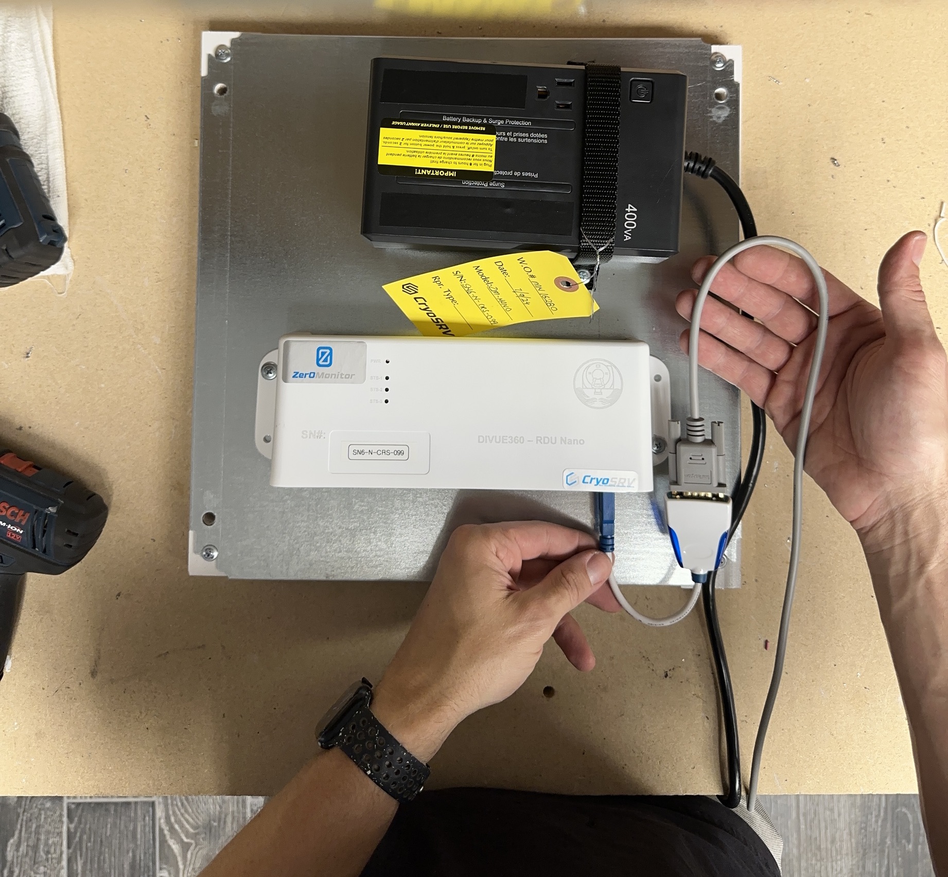
Installing USB Adapter and Null Modem Cable
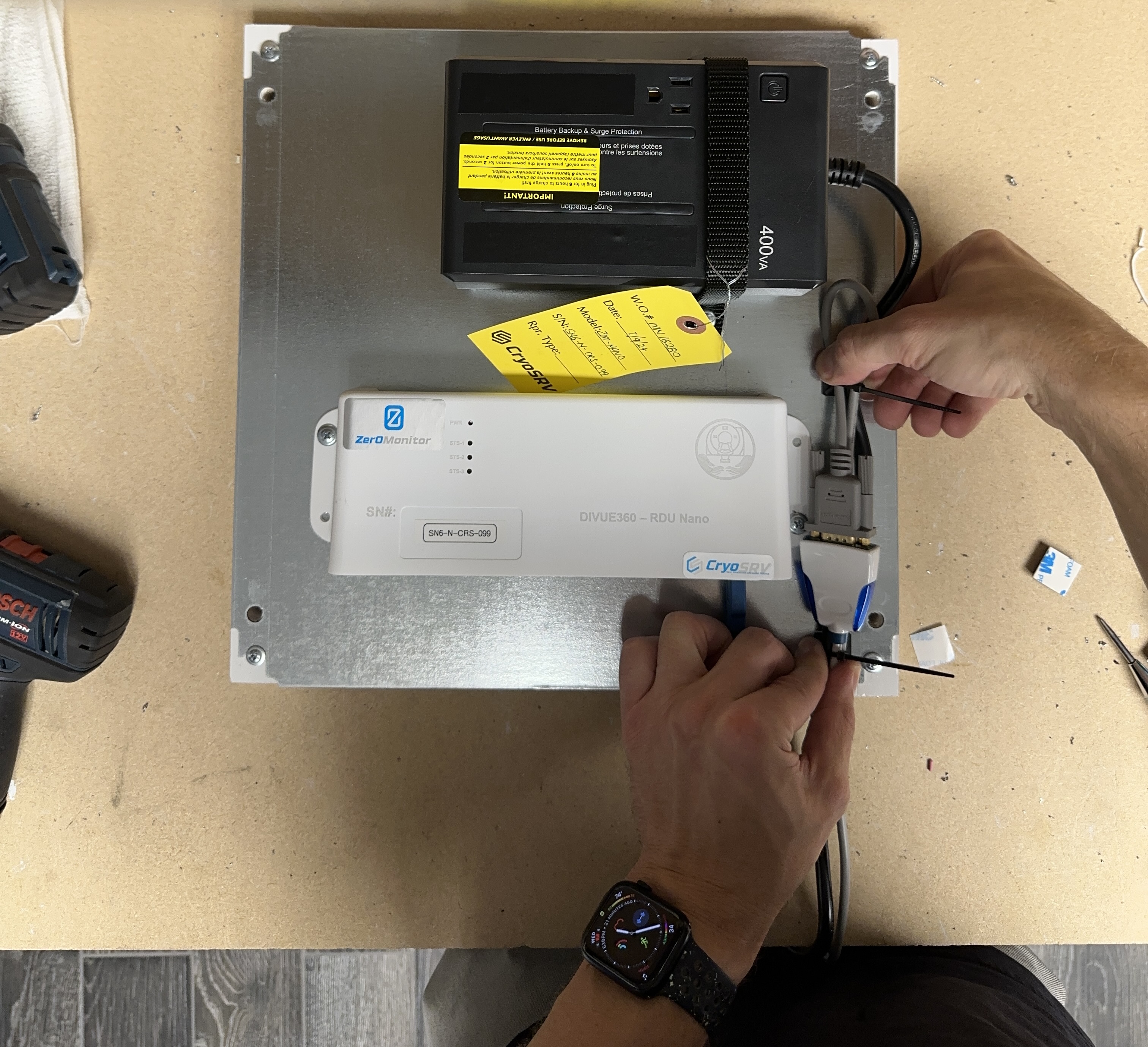
Connect the null modem cable to the USB adapter and plug the USB adapter into the remote monitor. The configuration should look like the image below.
Zip tie a loop in the null modem cable to power cable of the UPS with an adhesive pad on the bottom. Place another zip tie around the usb adapter to the UPS power cable with another adhesive pad on the bottom. The configuration should look like the image below.
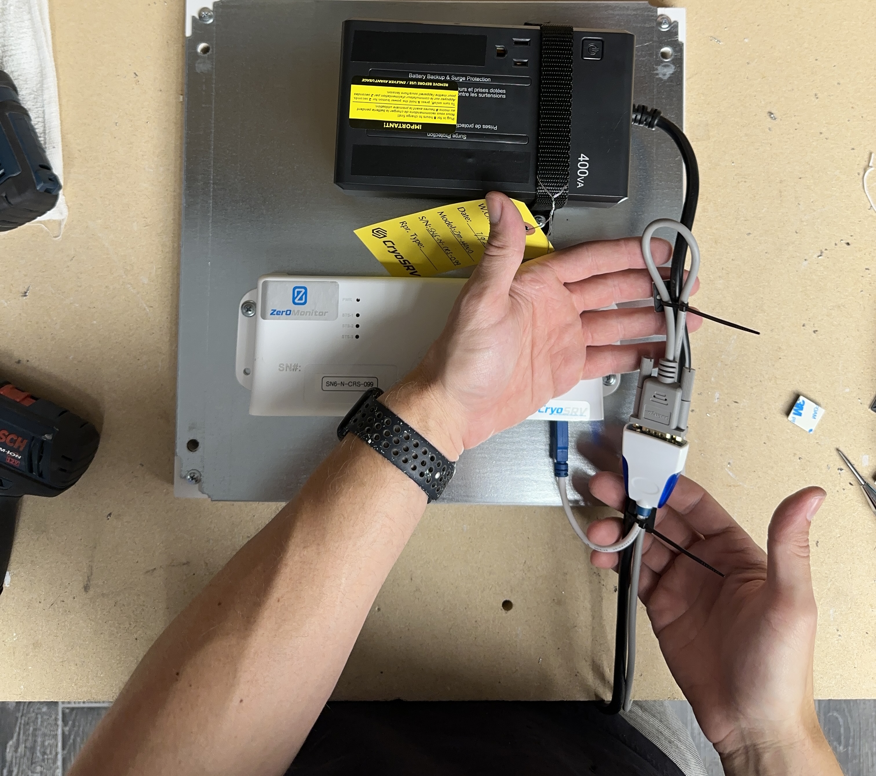
Remove the adhesive backing from the pads.
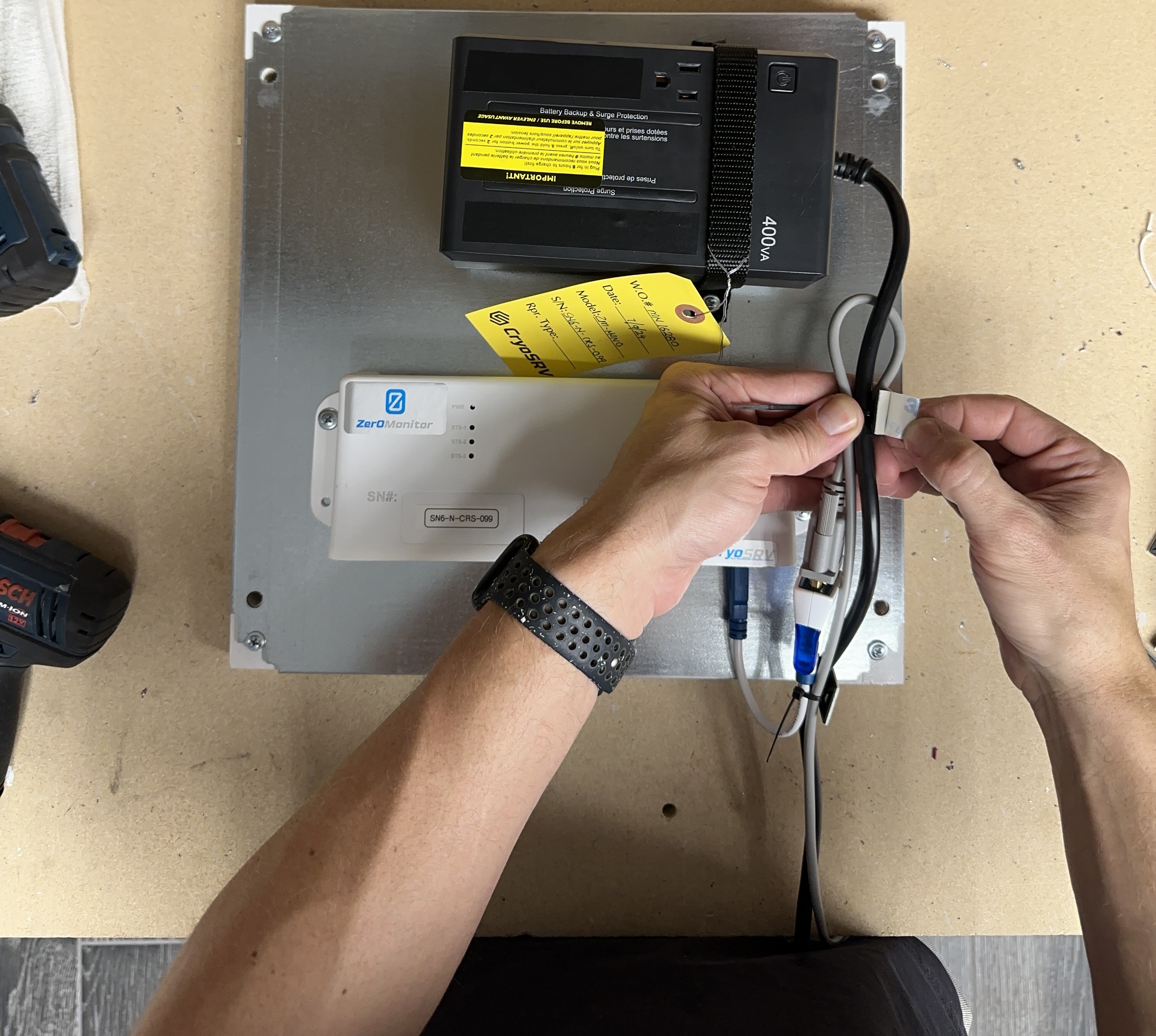
Firmly press the sticky pads down to the panel making sure to keep the tension off of the cable connections as well as staying clear of the through holes in the plate.
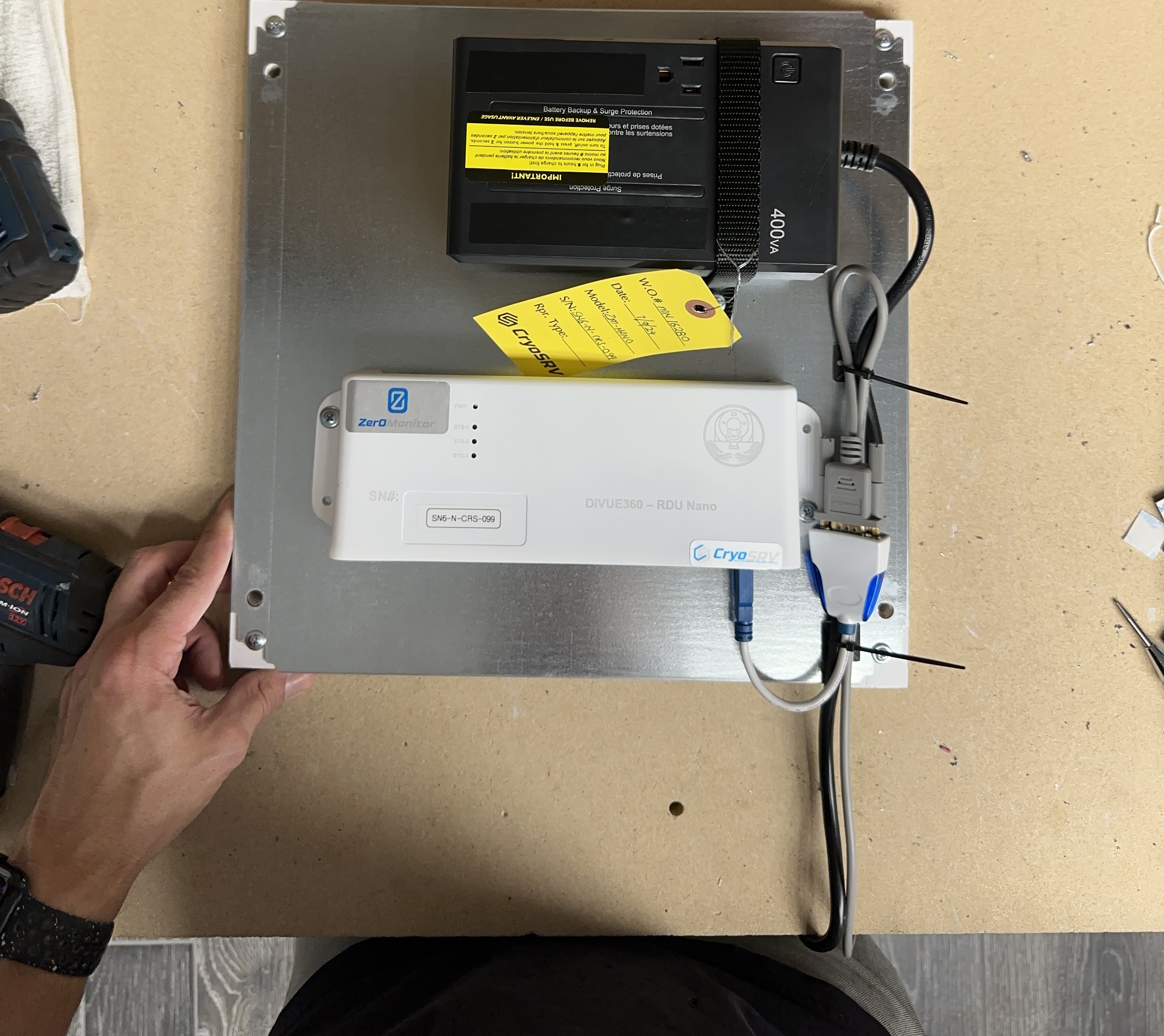
The final null modem and usb adapter configuration should look like below.
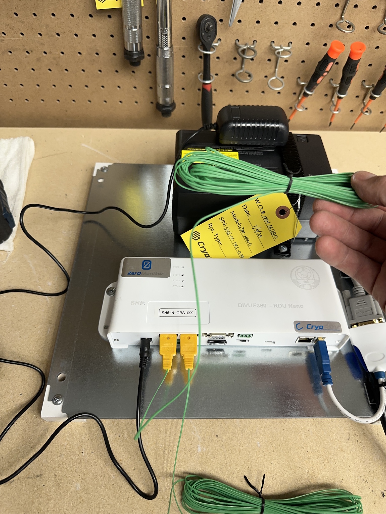
K-Type Thermocouples and Power Adapter
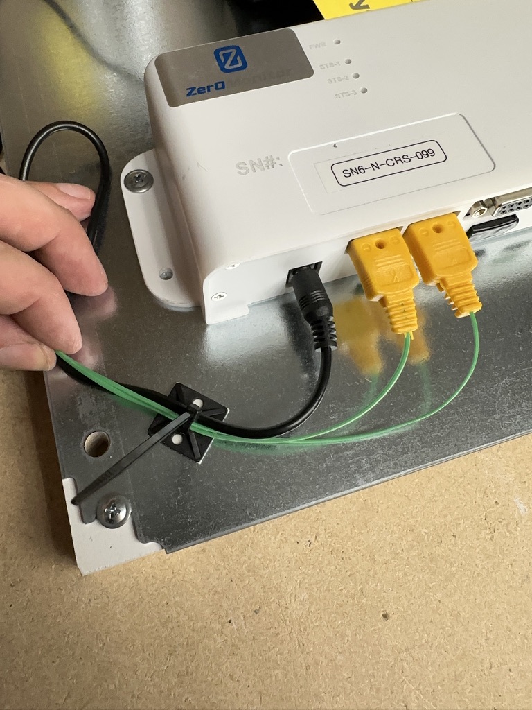
The K-Type thermocouples have two different sized prongs that indicate the (-)negative terminal and the (+)positive terminal. These must be connected directionally with the k-type thermocouple receptacle.
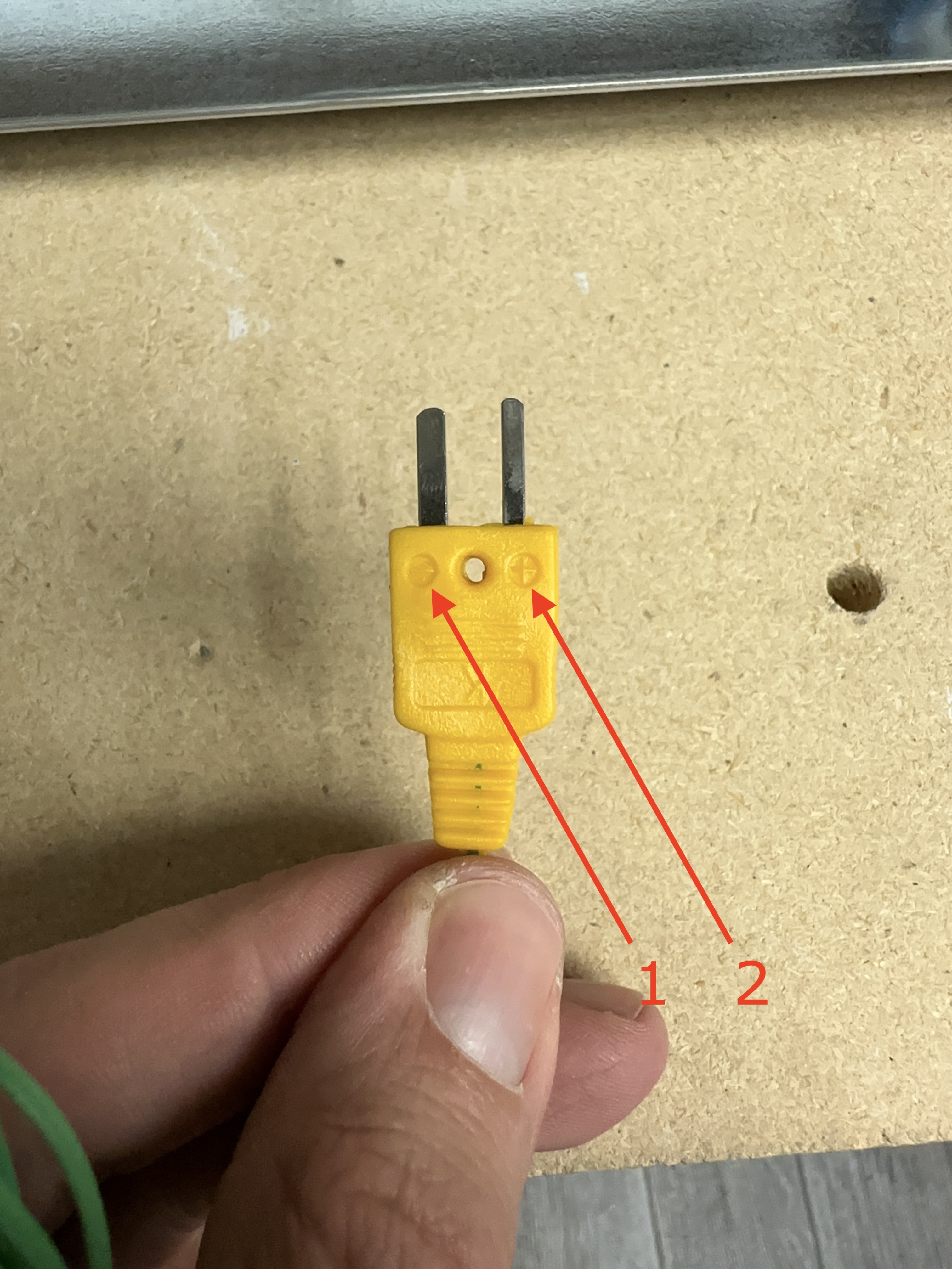
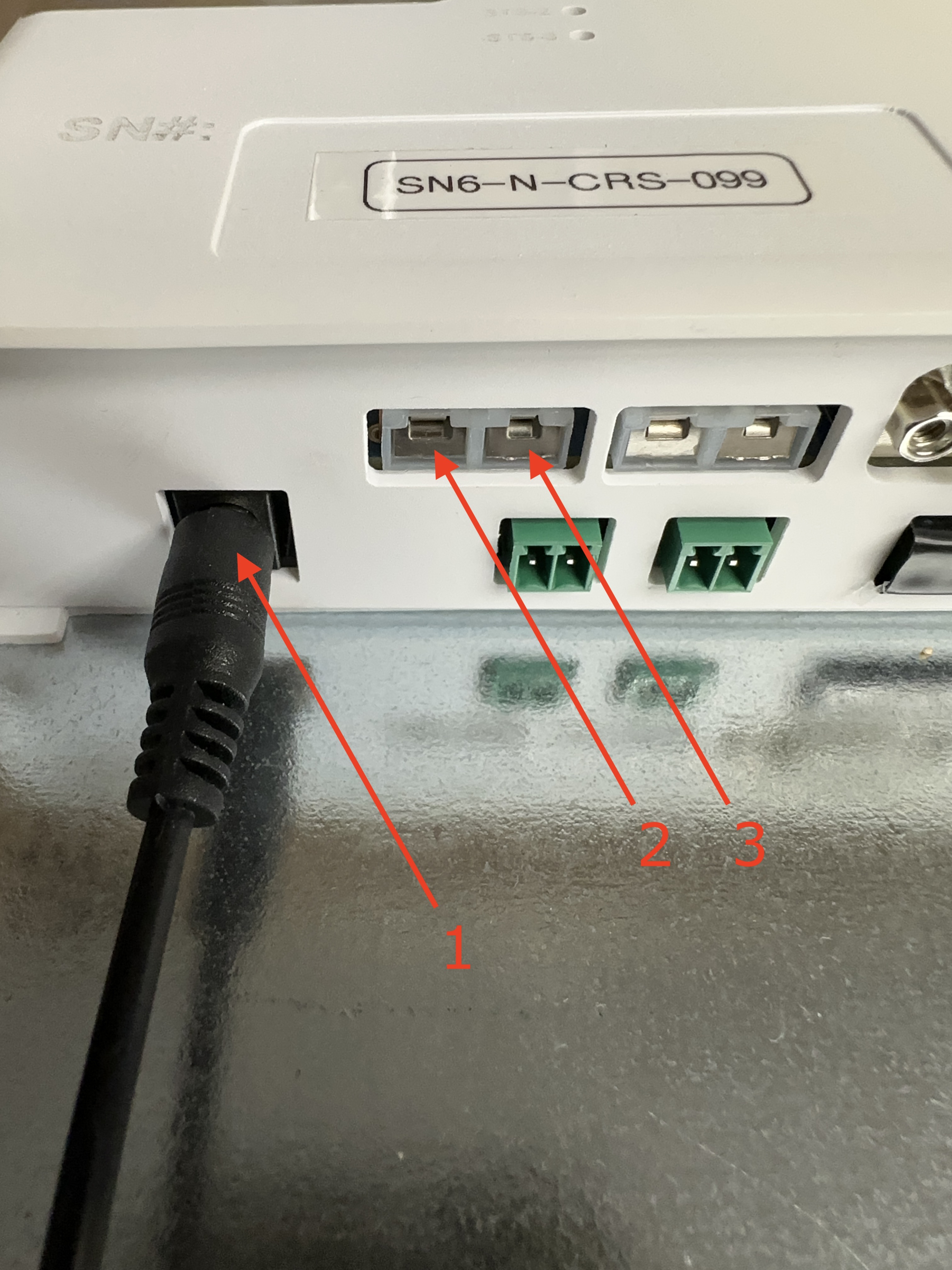
Connect the power cable to the device as well as the two k-type thermocouples. Take note of the matching positive(+) and negative(-) on the receptacle.
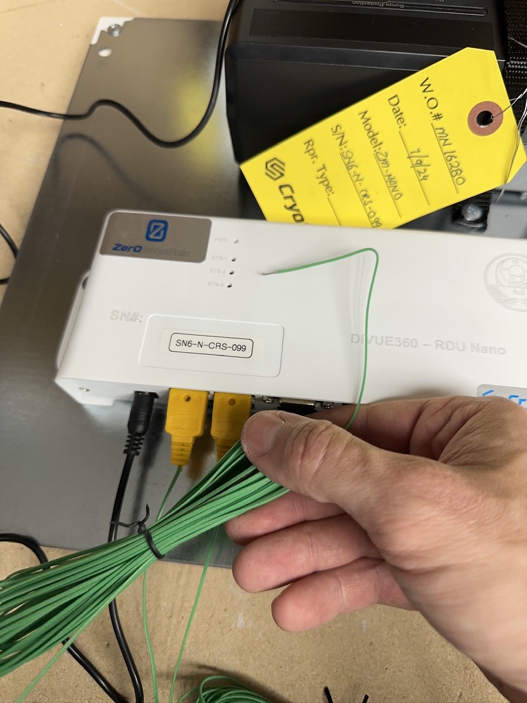
Labeling the Thermocouples
The thermocouples need to be labeled for the customer to connect to the proper chiller line. The receptacle to the left needs to be labeled "COLD" and the right most needs to be labeled "HOT".
Give yourself about a foot of cable from the plug to the roll of wire.
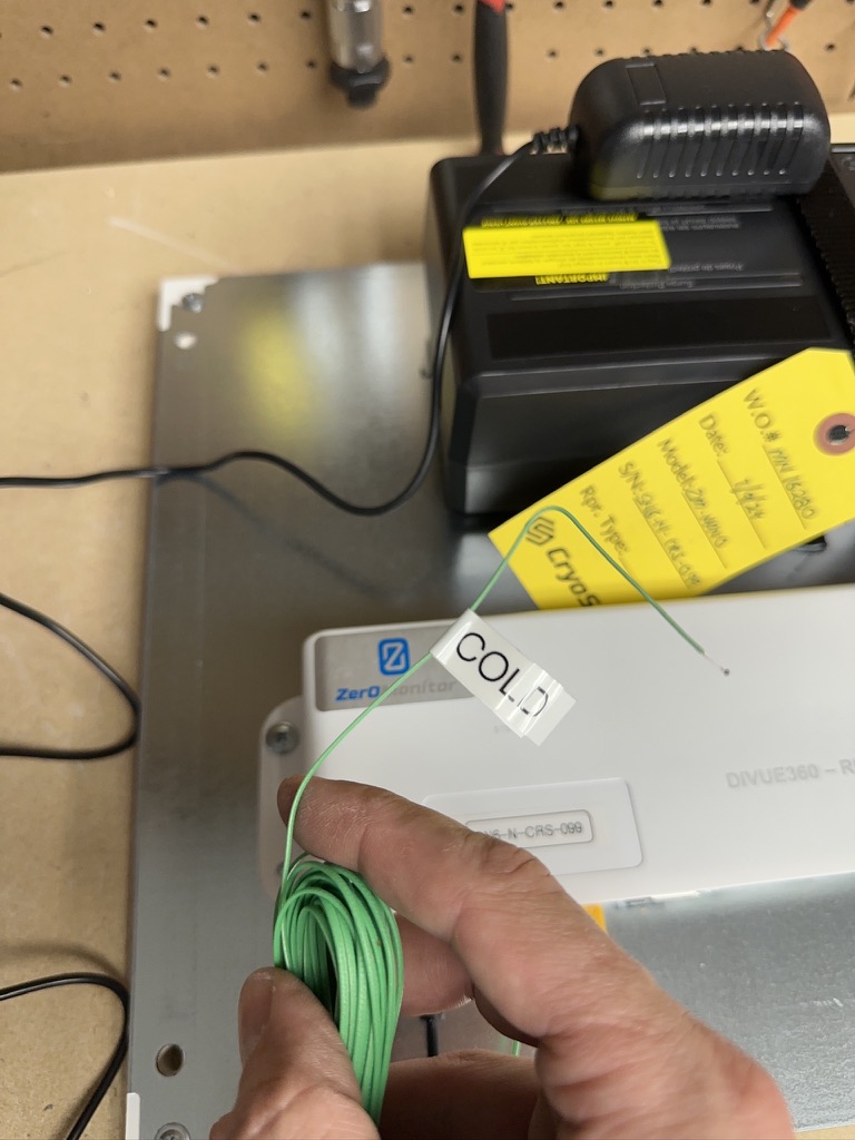
At the end of the thermocouple kink the thermocouple wire to prevent the label from sliding off.
Print out two labels using the label maker, one that identifies the COLD side and one that identifies the HOT side.
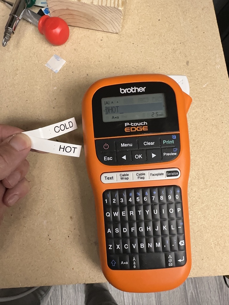
Attach the COLD label to the left thermocouple and the HOT to the right thermocouple.
Cable Management
The thermocouples and the power cable need to be zip tied to the adhesive pad and routed neatly as shown in the image below.
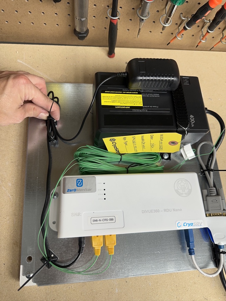
Store the thermocouple wire bundles in between the power supply and the remote monitor.
With the power adapter plugged in, roll up the loose power cable and zip tie next to the UPS.
Tip
This is a good time to clip all the long ends off of the zip ties.
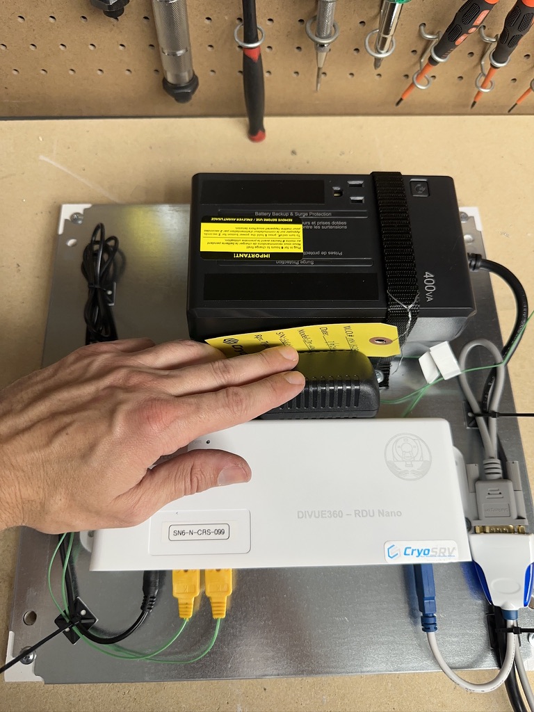
After the power adapter cable has been routed and fastened down, unplug the adapter and store it neatly in between the monitor and the UPS.
Wrap up the UPS power cable and wire tie neatly.
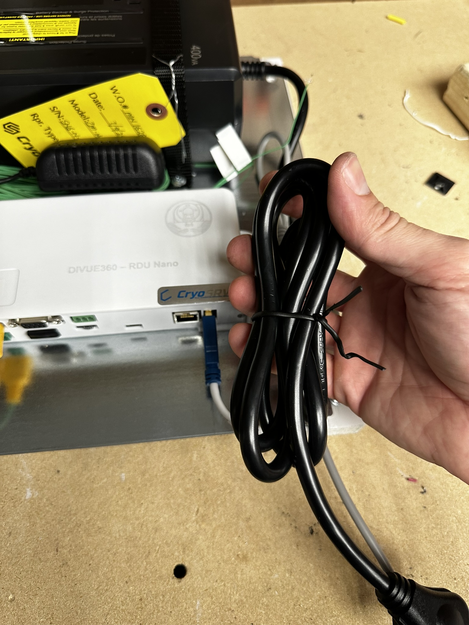
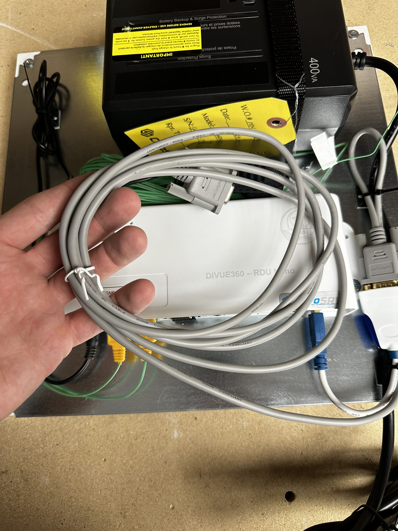
Roll up the null modem cable and wire tie it.
Add the rolled up RJ45 ethernet cable.
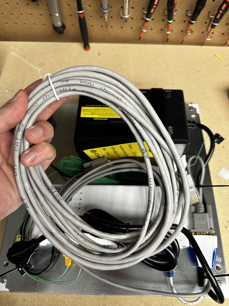
Organize all the components on top of the panel for packing.
Complete
Bring the completed panel to logistics for stock.