Warning
Incomplete work instructions.
F-50H-CM
Take note of the color of the bag protecting the WO tag and also repair type written on the tag and printed out on the paper work as outlined in the Test Paperwork work instructions.
Servicing Instructions
The repair instructions will be pre-populated with information regarding any steps that will help with the repair. There are also customer notes located in the Trello card for reference on customer supplied units.
Scope
The scope of this procedure is to cover the servicing section of a F-50 Compressor unit. Servicing includes several processes that will help optimize the operation of the compressor unit in the field. Servicing needs to be done on every F-50 compressor unit received at the CM lab.
Cross Reference Forms
| Form | |
|---|---|
| CM Test Paperwork | |
| CM Check In Form | |
| CM Descale Oil Change Evac Form |
Effectivity
This procedure is applicable to all Sumitomo F-50 compressor units.
Definitions
| Term | Definition |
|---|---|
| Unit | Compressor underling servicing |
A. Product Information
When receiving in a helium compressor it is important to gather information about the unit as it was received. This includes the physical condition as well as the functionality. If there is physical damage or visible defects, take images of the areas and upload them to the Trello card.
Notes from Field
"Notes from field" means information about the compressor when it was running on a system. This can be information from the customer or technician who performed the troubleshooting or changed the compressor. This information can sometimes be automatically populated onto the page for printing. Other times the technician will have to investigate and record what is discovered.
Tuning Performed
Tip
Durning the initial repair skip over this.
This field is used for documenting the repairs made to helium compressor after a failure is recorded.
B. Initial Evaluation Info
When the compressor arrives from the customer it is important to capture all of the information about the compressors status before making any changes. The status upon arrival will assist with troubleshooting compressors have failed rather than being routinely maintained.
Initial Compressor Pressure
The F-50H helium compressor has two pressure gauges located on the front of the unit. There is a high pressure gauge and a low pressure gauge. Record the value indicated on the high pressure gauge. If there is a discrepancy between the high and low pressure gauges note the difference.

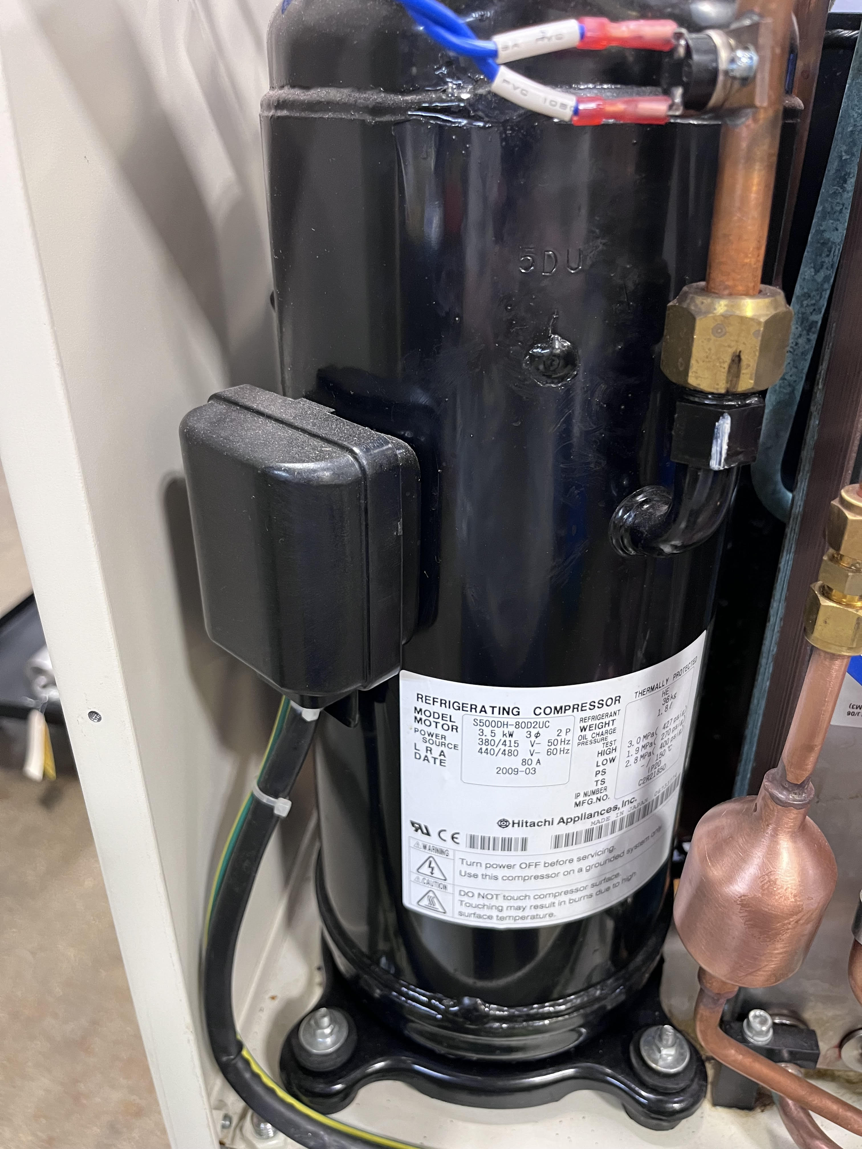
Capsule Resistance
The capsule resistance is taken at the lugs of the capsule itself.
Locate the enclosure where the lugs are located and remove the cover.
Danger
DO NOT ATTEMPT TO MEASURE THE RESISTANCE WITH POWER RUNNING TO THE HELIUM COMPRESSOR.
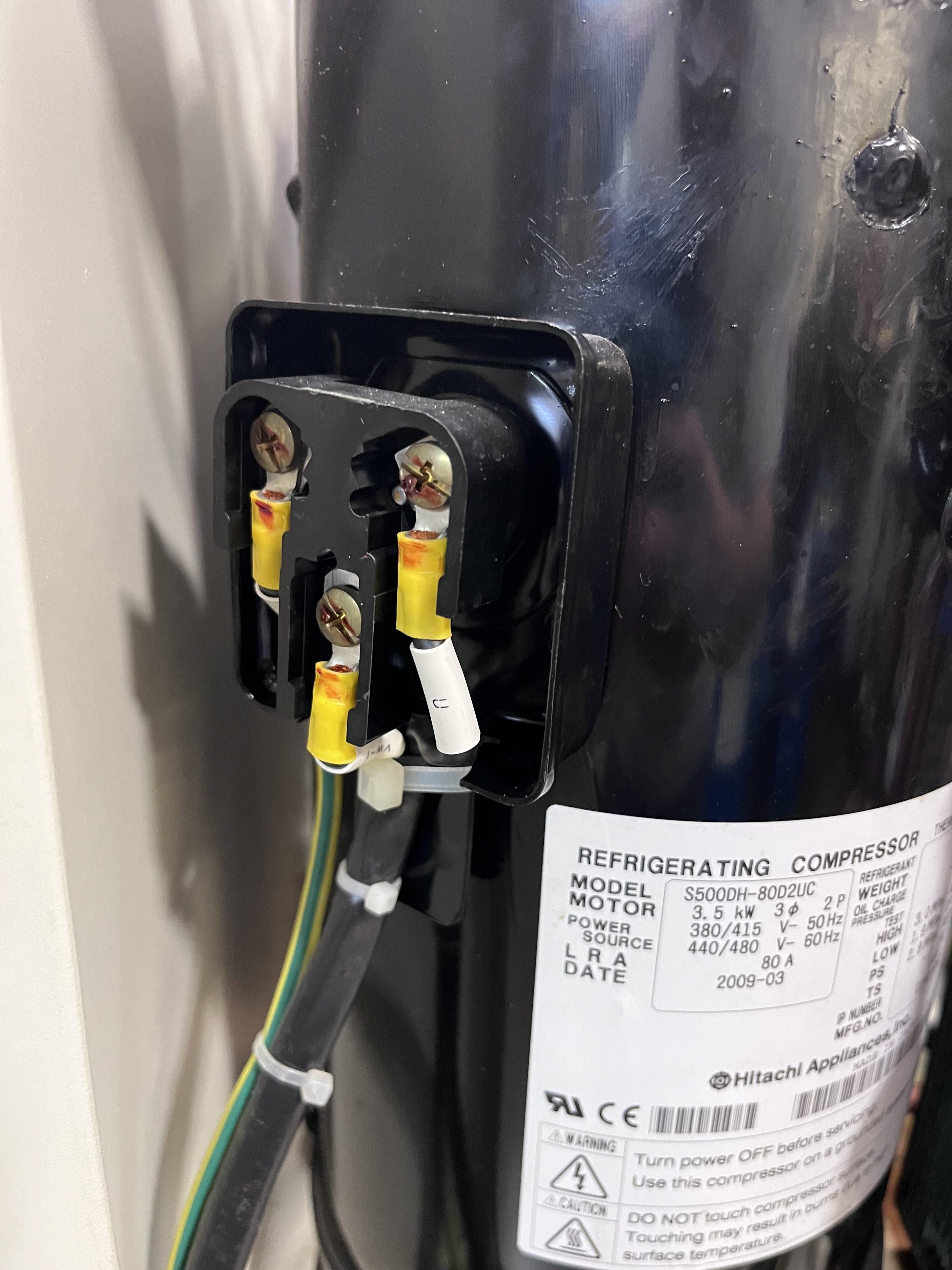
With the cover removed, use a digital volt meter to measure the resistance on the motor windings. Record the following configurations.
| A | B | C | G | |
|---|---|---|---|---|
| A | n/a | 2.4 | 2.4 | ∞ |
| B | 2.4 | n/a | 2.4 | ∞ |
| C | 2.4 | 2/4 | n/a | ∞ |

Initial Comp. Hrs
The initial compressor hours will be found on the on the hour meter located on the front of the helium compressor. This model of helium compressor doesn't need to be powered for this function.

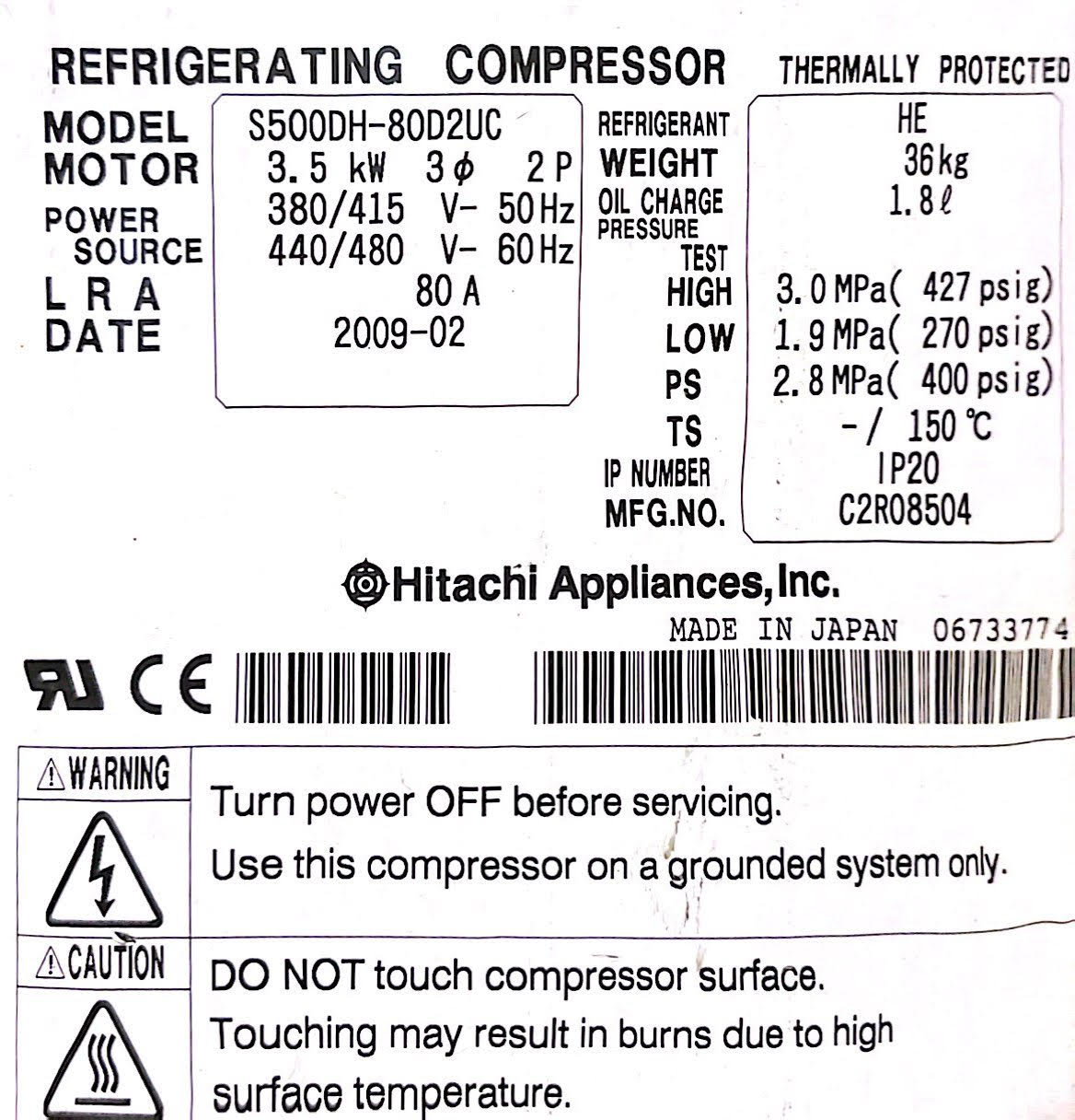
Component Serial Numbers
Note
If this is in fact a prior CryoSRV Rebuild the serial numbers for these units should already exist on the unit.

Capsule Serial Number
Each capsule should have a label affixed to the side from the manufacturer. Use the serial number issued for the capsule.
If there is no serial number or the label is unreadable a serial number needs to be issued to the capsule. Attach the serial number to the location imaged below for the capsule.
Heat Exchanger Serial Number
Each heat exchanger should have a label affixed to it with a serial number. Use that serial number for records.
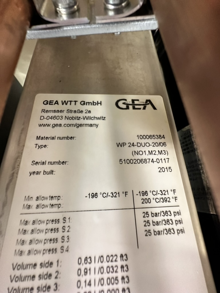
If there is no serial number or the label is unreadable a serial number needs to be issued to the heat exchanger. Attach the serial number to the location imaged below for the heat exchanger.

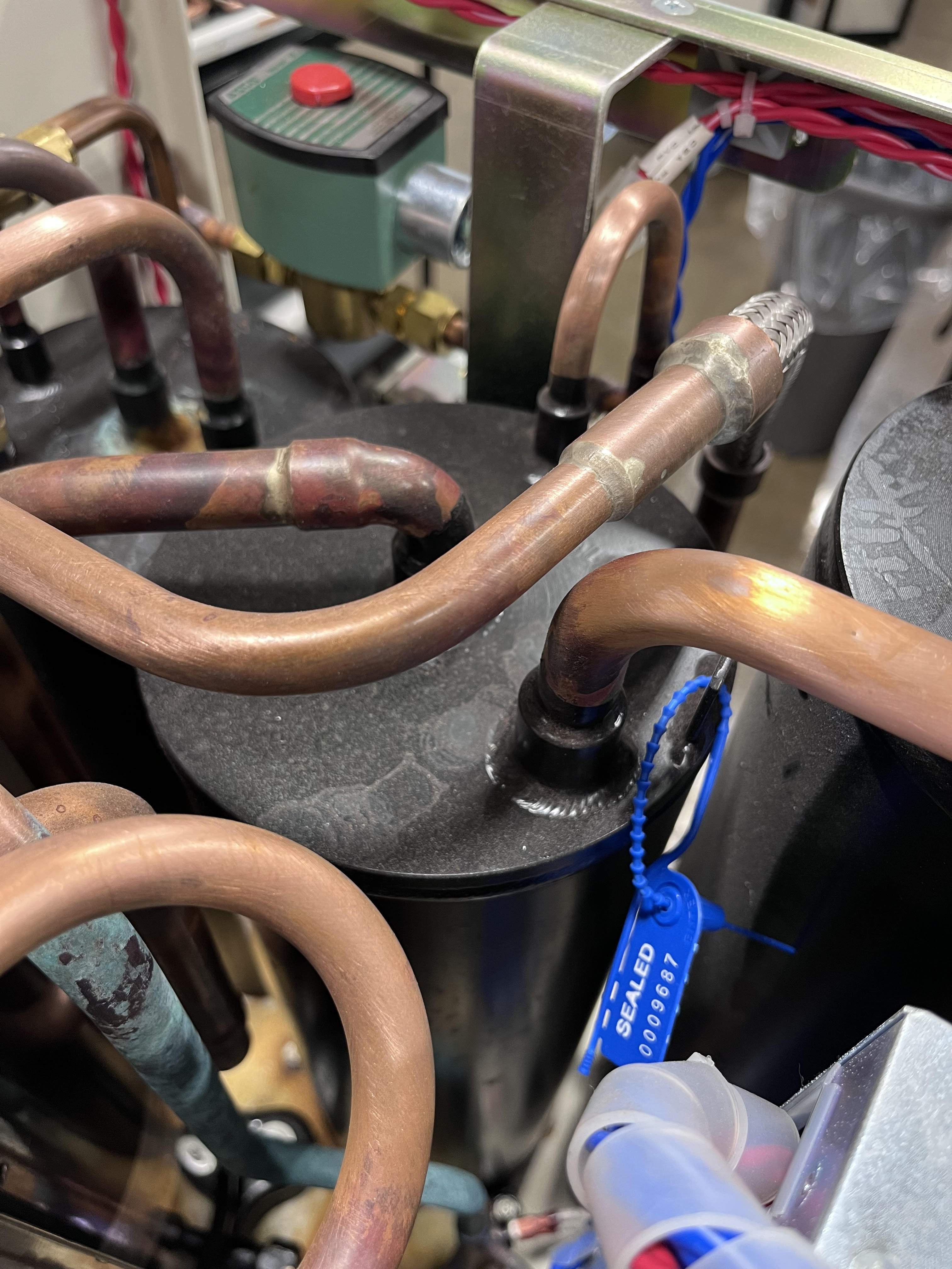
Oil Separator Serial Number
Attach the serial number to the location imaged below for the oil separator.
Power Taps Configuration
Inside the electrical box on the unit there is a series of power taps that can be selected for what type of incoming power is available. Note the configuration.
Remove the electrical cover on the side of the control box.
Note
If a customer has shipped the unit from another country it is possible that the taps need to be returned to their original setting before being shipped back out.
Warning
The power taps must be set to 460V power or damage to the controls could result.
Bump Test Results
The bump test is performed by wiring up the helium compressor and applying power briefly to the capsule to be sure that the contactor will pull in and the capsule will build pressure.
Wiring The Compressor
The F-50H-CM requires an open whip style connector with the terminated wires exposed.
Feed the wire through the bracket and be sure to properly strain relief the whip by fastening the nut.
The order of the wires matters because they correspond to a specific rotation. The wires must correspond to the table below.
| Terminal | Color | Leg |
|---|---|---|
| 1 | RED | 1 |
| 2 | WHITE | 2 |
| 3 | BLACK | 3 |
| G | GREEN | G |
Safely Cover The Terminal Block
After the compressor is properly wired and strain relieved, the terminal block must be covered.
Connecting To Power
Warning
Make sure the helium compressor is in the following configuration before moving forward.
| Switch | Status | Description |
|---|---|---|
| 1 | OFF | Power |
| 2 | LOCAL | Remote Drive |
| 3 | OFF | Cold Head Drive |
| 4 | OFF | Main Breaker |
| 5 | ON | Cold Head Breaker |
| 6 | ON | Capsule Breaker |
Bump The Compressor
Connect the helium compressor to main power.
Warning
The helium compressor must have at least 1.0MPa static pressure in order to perform the bump test or the unit may fail the bump test.
Rotate the main breaker to the on position.
Toggle the power switch to the on position and making sure that the pressure gauge builds pressure until the unit powers off on low pressure suction. Do not let the unit run for more than 5 seconds.
Monitor that the pressure builds on the head pressure gauge.
C. Quality Control Check # 1
The purpose of these quality checks is to make sure that the unit is clean and that after refurbishment that the unit doesn't need to be disturbed. If each item on the check list is acceptable initial in the space available. If the unit is not acceptable, document the area of concern in the Trello card with images and text. Tag @spatil in the card and transfer it to the CM - MEETING AGENDA list.
Base Clean
Controls Cleaned
Frame Cleaned
Plumbing Cleaned
Descaling Data
Pre-Descaling Water Flow
Pre-Descaling is the process of measuring the water flow and water pressure in the unit before the Acid Wash is done. This will help to determine if there will be any improvement in water flow and water pressure post the Acid Wash process.
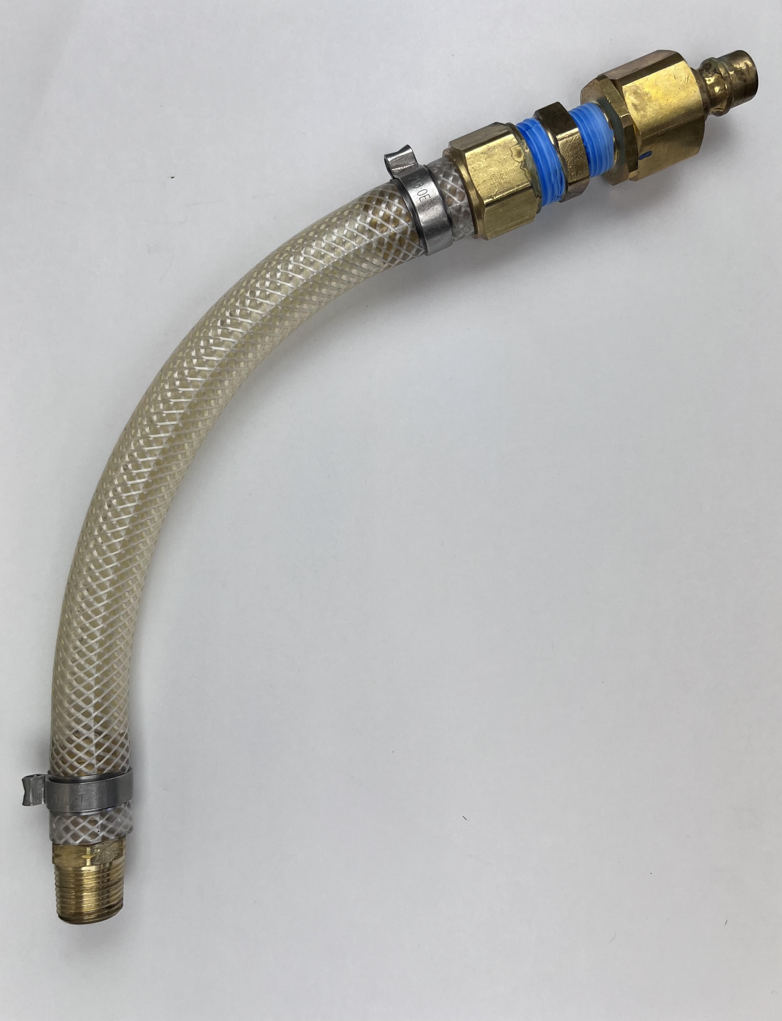
R ⅜ Fittings
Obtain Water Inlet and Outlet fittings.
Note
Some F-50 units require R⅜ male thread fittings. A label will be located on the unit that would indicate if the specific unit require these fittings.

Warning
Using standard NPT fittings will damage the compressor if the R⅜ fittings are called out.
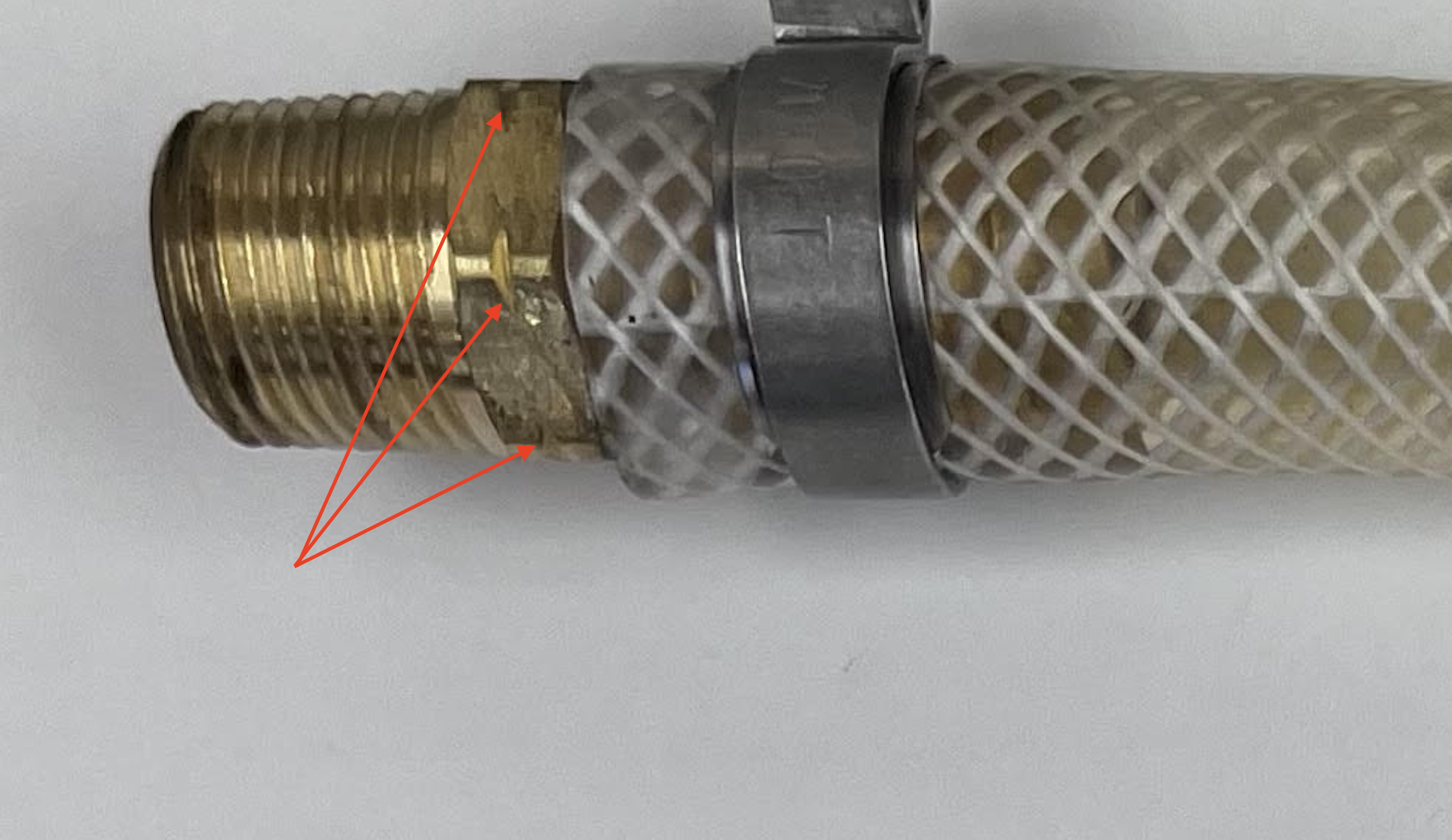
Tip
R⅜ tapered fittings are manufactured with notches in the hex faces to distinguish them from standard ⅜ NPT fittings.
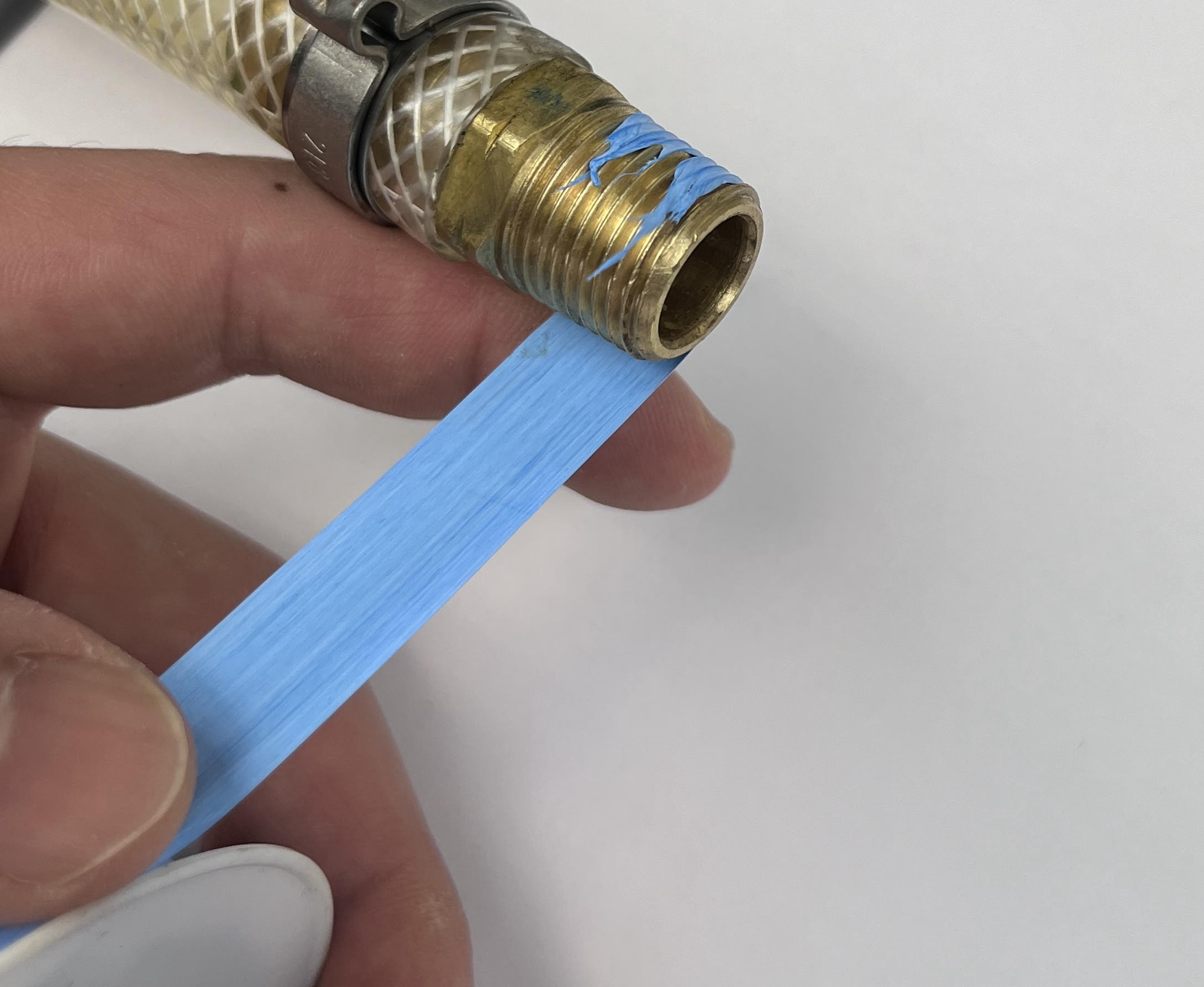
Applying PTFE Tape
Obtain PTFE Tape
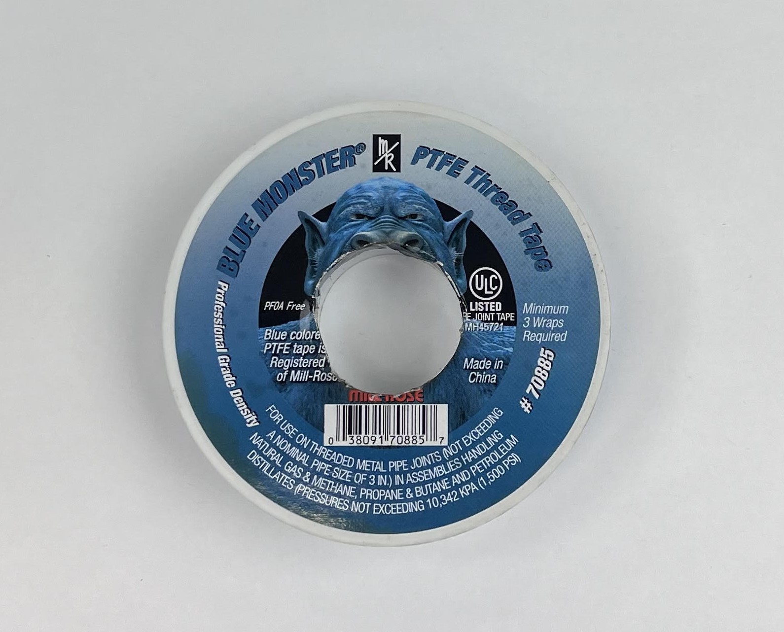
Apply one layer of PTFE tape on the male threads before installing the fittings into the unit.
Note
Apply the PTFE Tape clock-wise facing the fitting to avoid tape coming off while installing the fittings.

Install the fittings while making sure not to apply more than 15 N-m of torque on each fitting.

The fittings will remain installed on the unit throughout servicing and testing.
Connect City Water
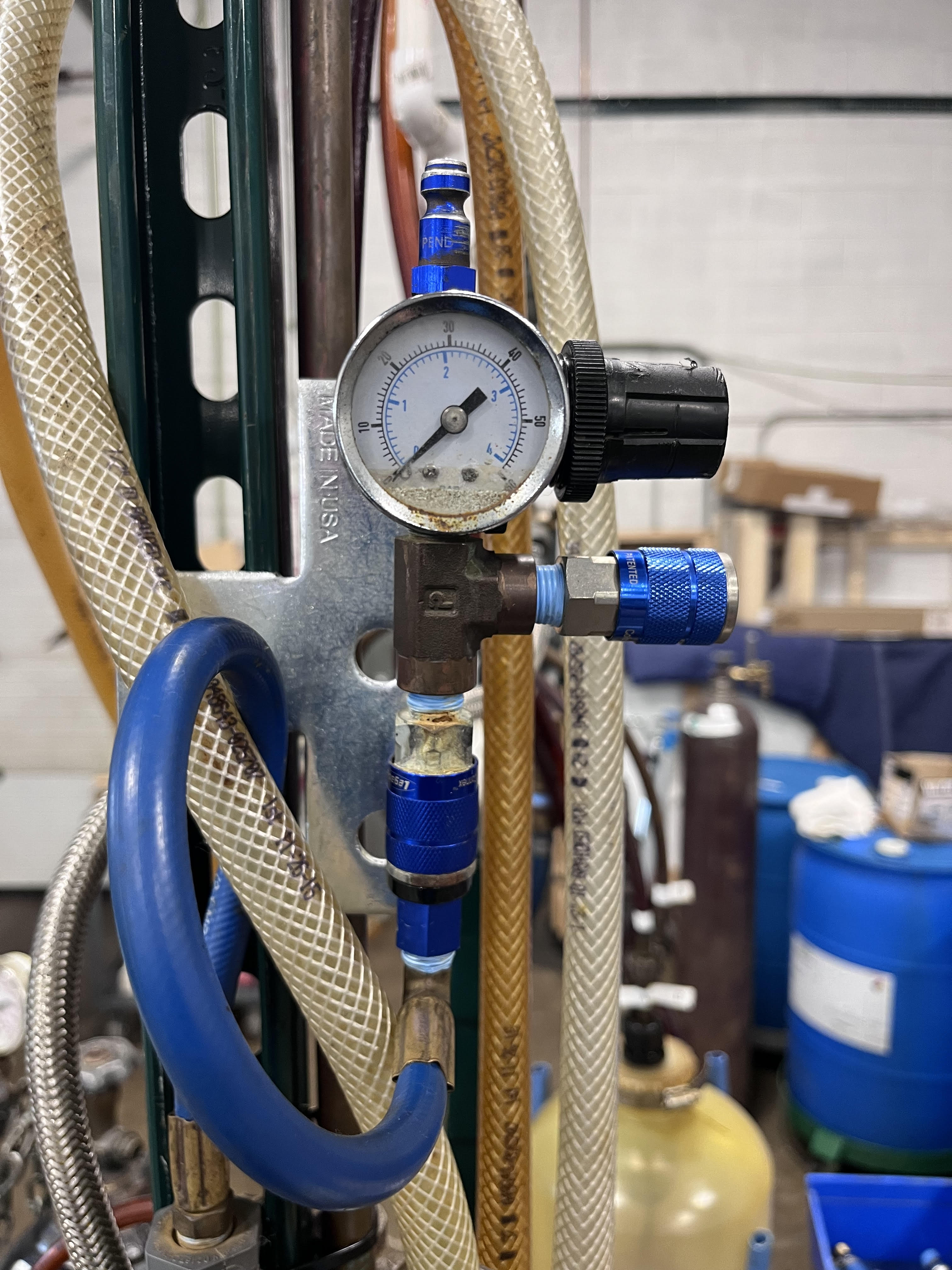
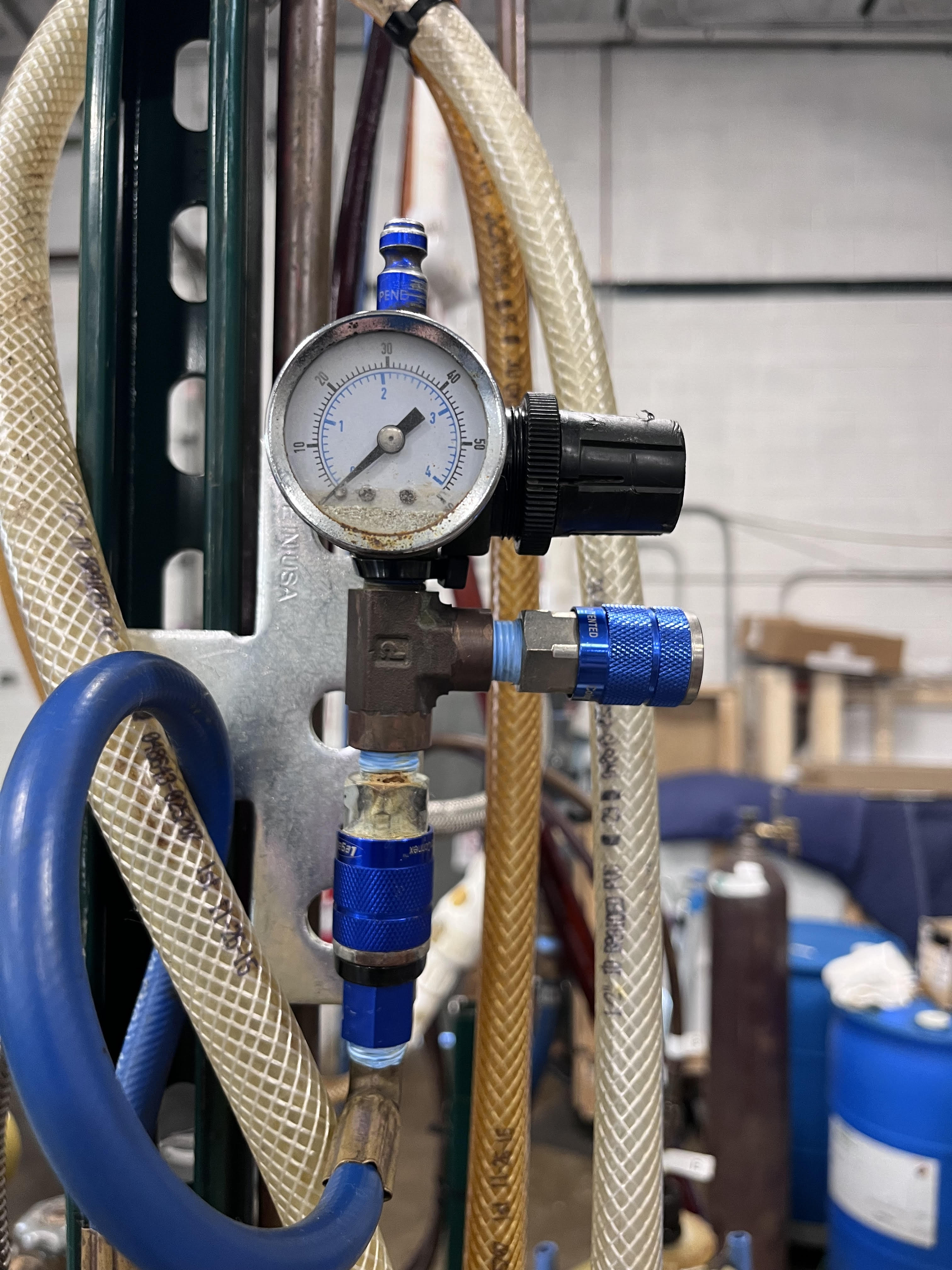
City Water Manifold Configuration
Verify the following configuration before connecting the water lines.
The water supply valve must be in the off position.
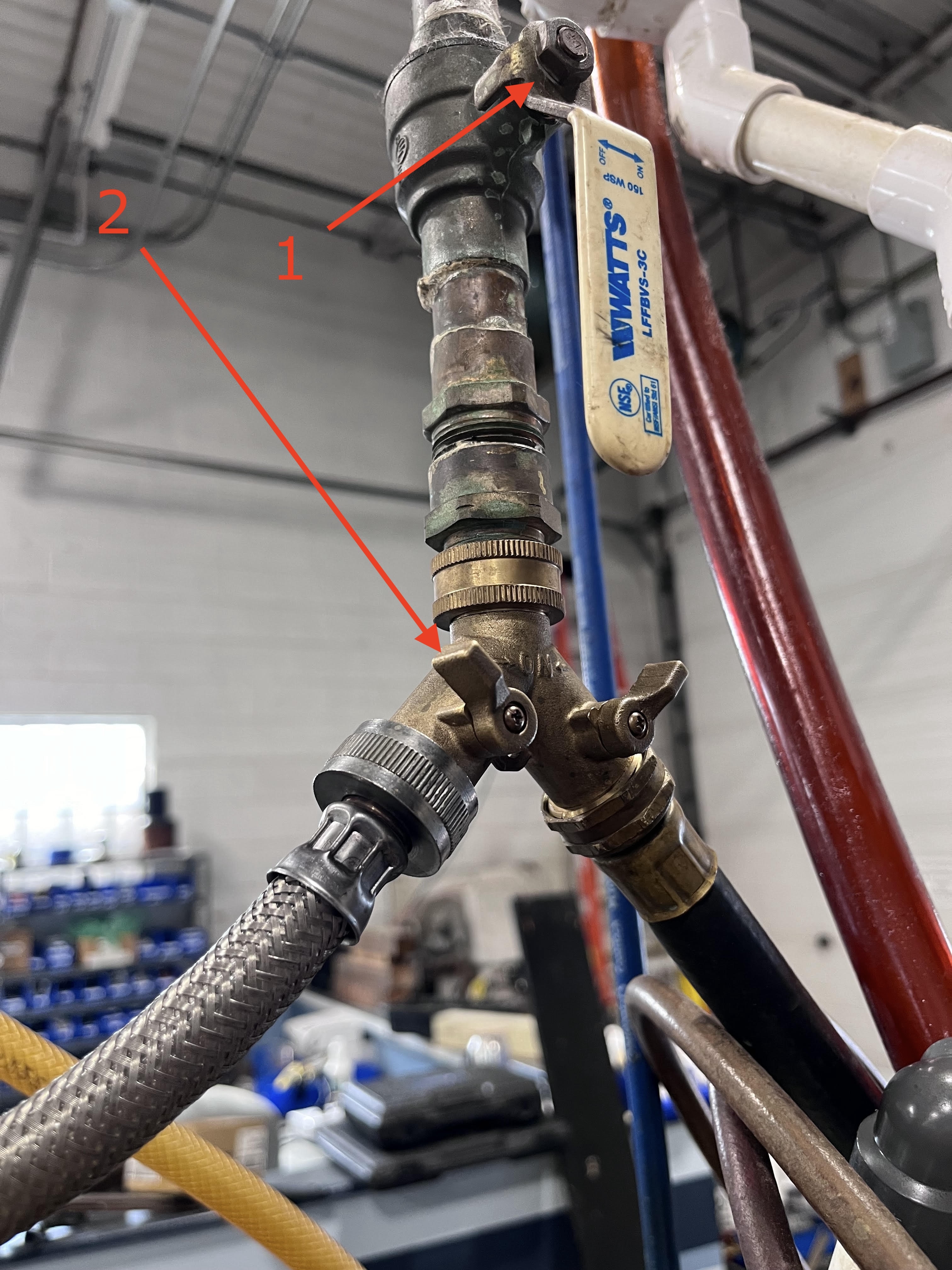
Connect City Water
Once the fittings have been installed, connect the Water Return Line on the Water Return Outlet. Connect the Water Supply Line on the Water Supply Inlet.
Note
Make sure the pneumatic line is connected to the Pressure Regulator before proceeding to the next step.
Initial Heat Exchanger Flush
Open the Water Supply Valve.
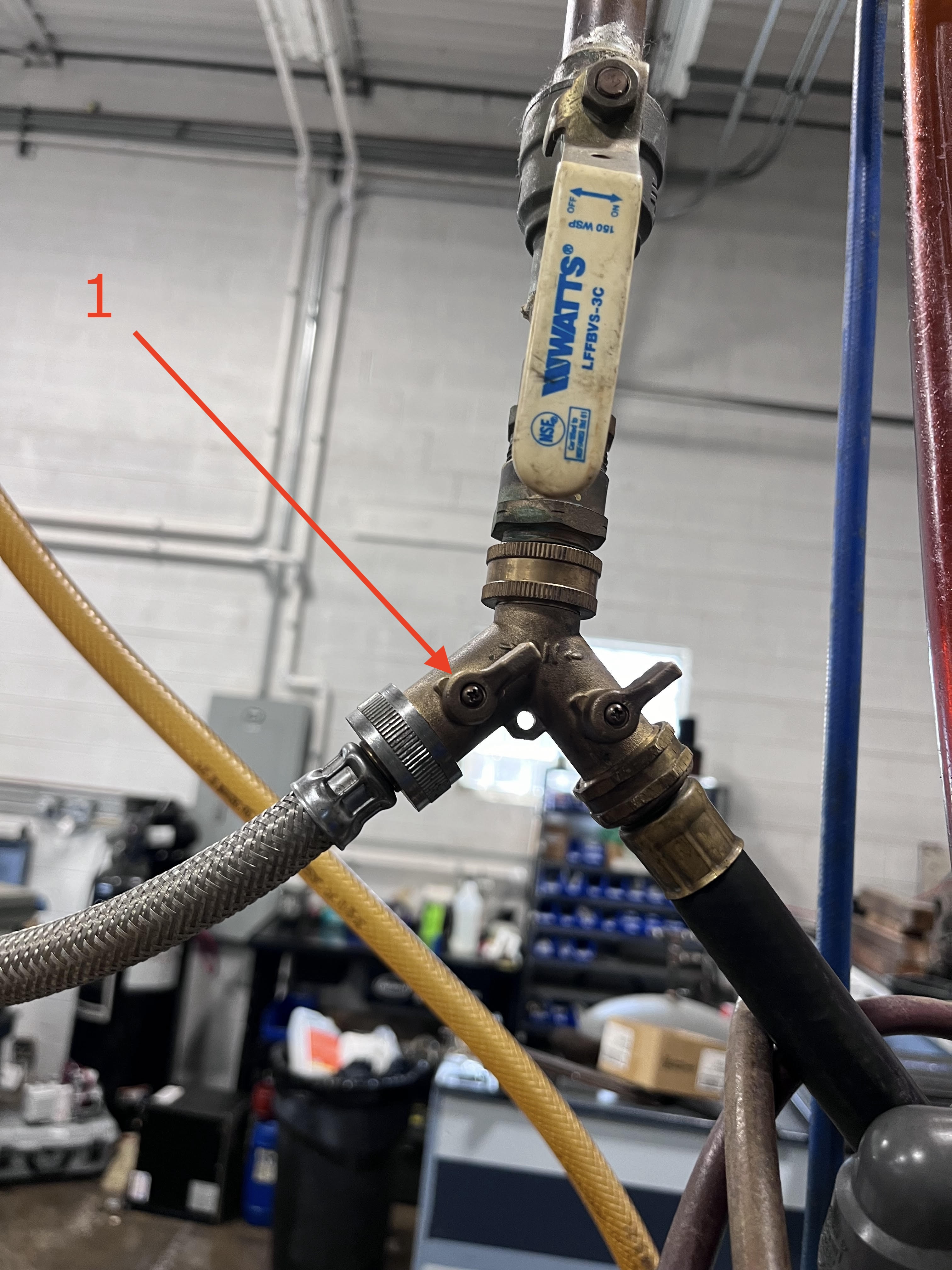
On the Water Flow Valve, turn the handle of the valve to the UP position to allow water to flow to the unit.

Allow the water to flow for 10 seconds before taking the reading of the Water Flow rate and the Water Pressure. Note the Water Flow rate and Water Pressure on your CM Test Paperwork.
Note
Note Water Pressure reading in PSI and flow in GPM
Purge Out The Water
Set the pressure on the regulator for 15psi.

On the Water Flow Valve, turn the handle of the valve to the LEFT position to allow air to flow and blowout water from the unit.
Run air into the unit until no more water is coming out of the Water Outlet. Disconnect Water Supply and Return Lines from the unit. Unit is now ready for the Acid Wash.
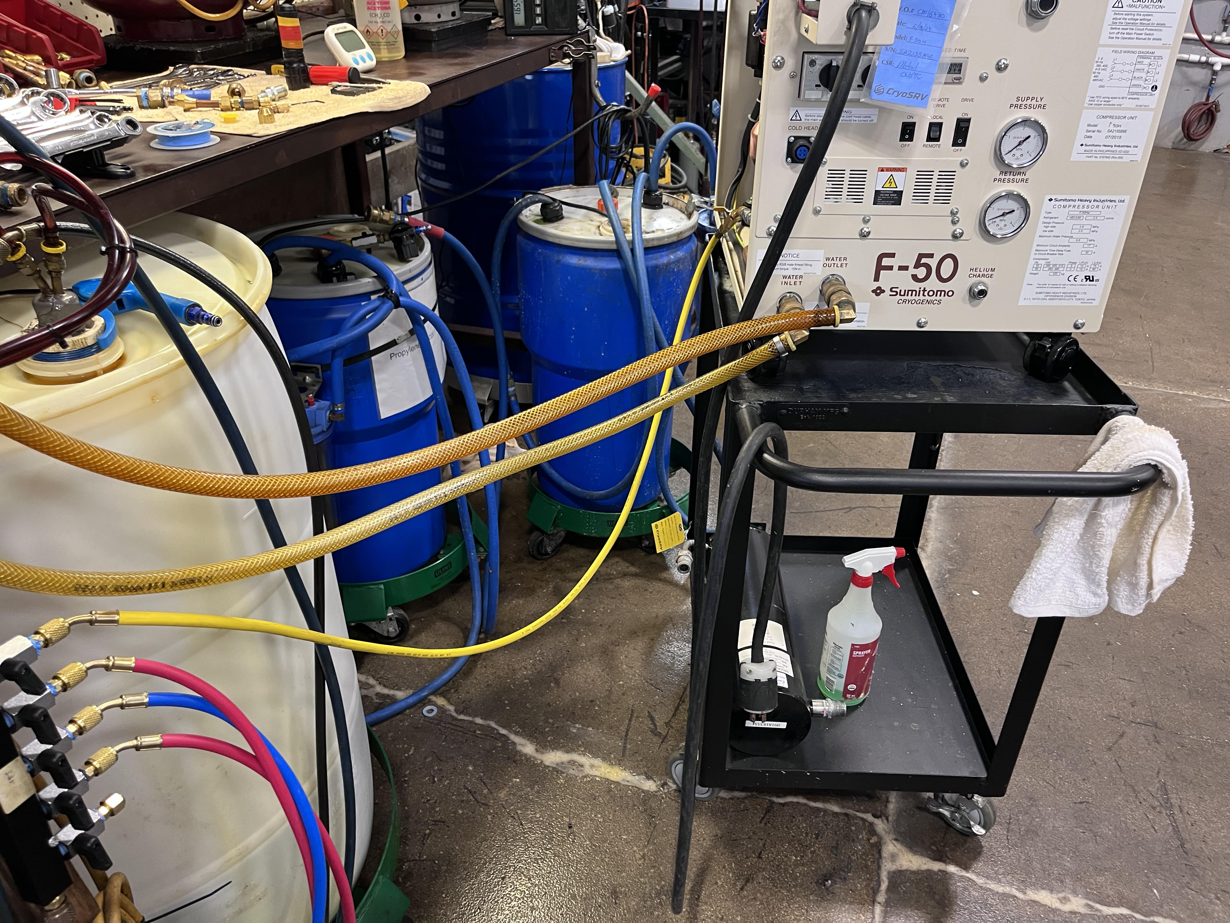
Acid Wash
Acid Wash is the process of running an acid/water mix through the unit water lines to help dissolve any sediment buildup in the water lines within the unit.
Note
For the acid/water mix utilize the Rydlyme/Water Mix
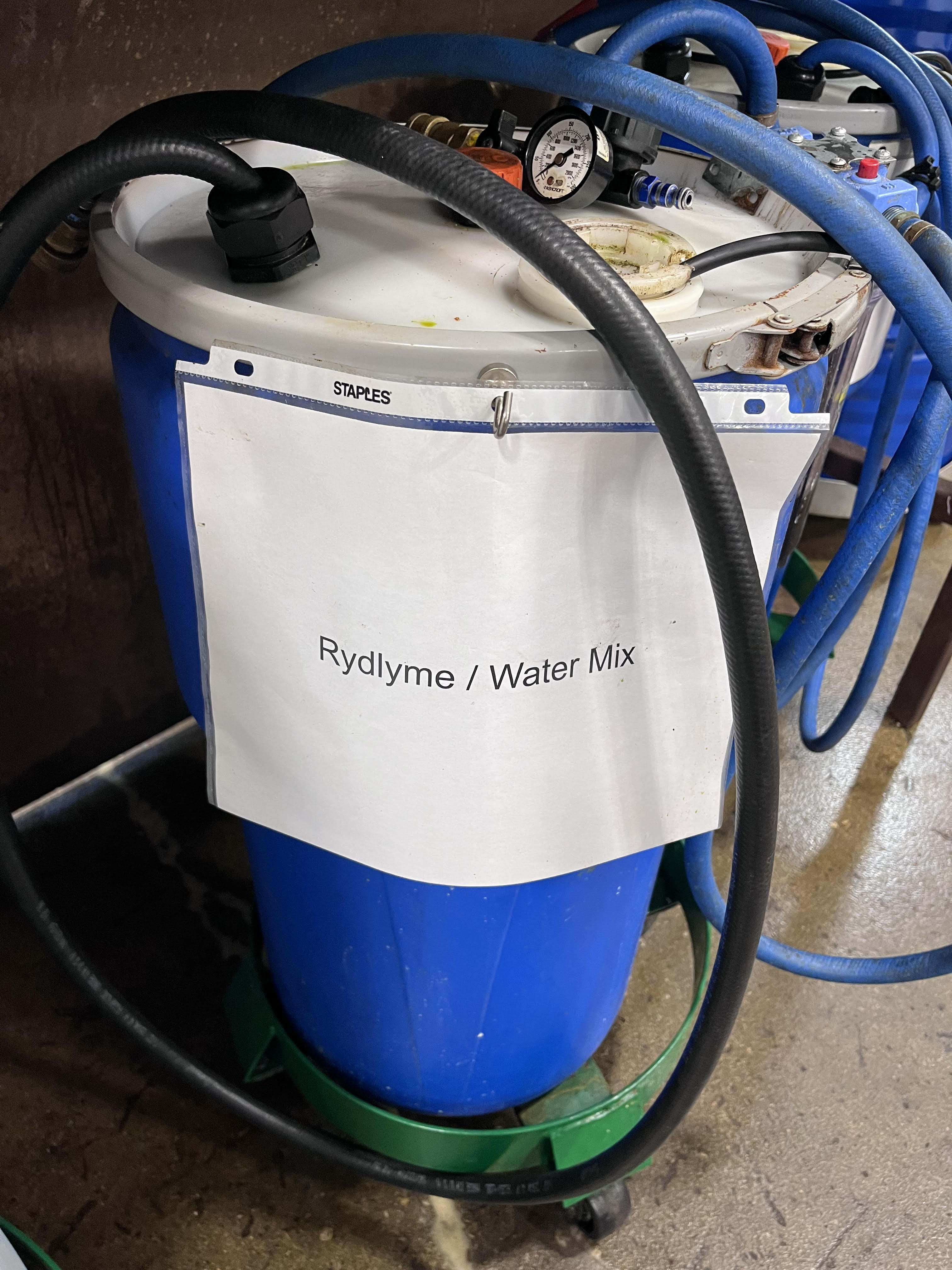
Find the Rydlyme/Water Mix barrel. The barrel will have two main hoses (lines) and one power cable connected to it.
Connect the Rydlyme/Water Mix Return Line to the Return Outlet on the unit.
Note
The Rydlyme/Water Mix Return Line is the line coming out of the tank and connects to a filter found on the outside of the Rydlyme/Water Mix barrel.
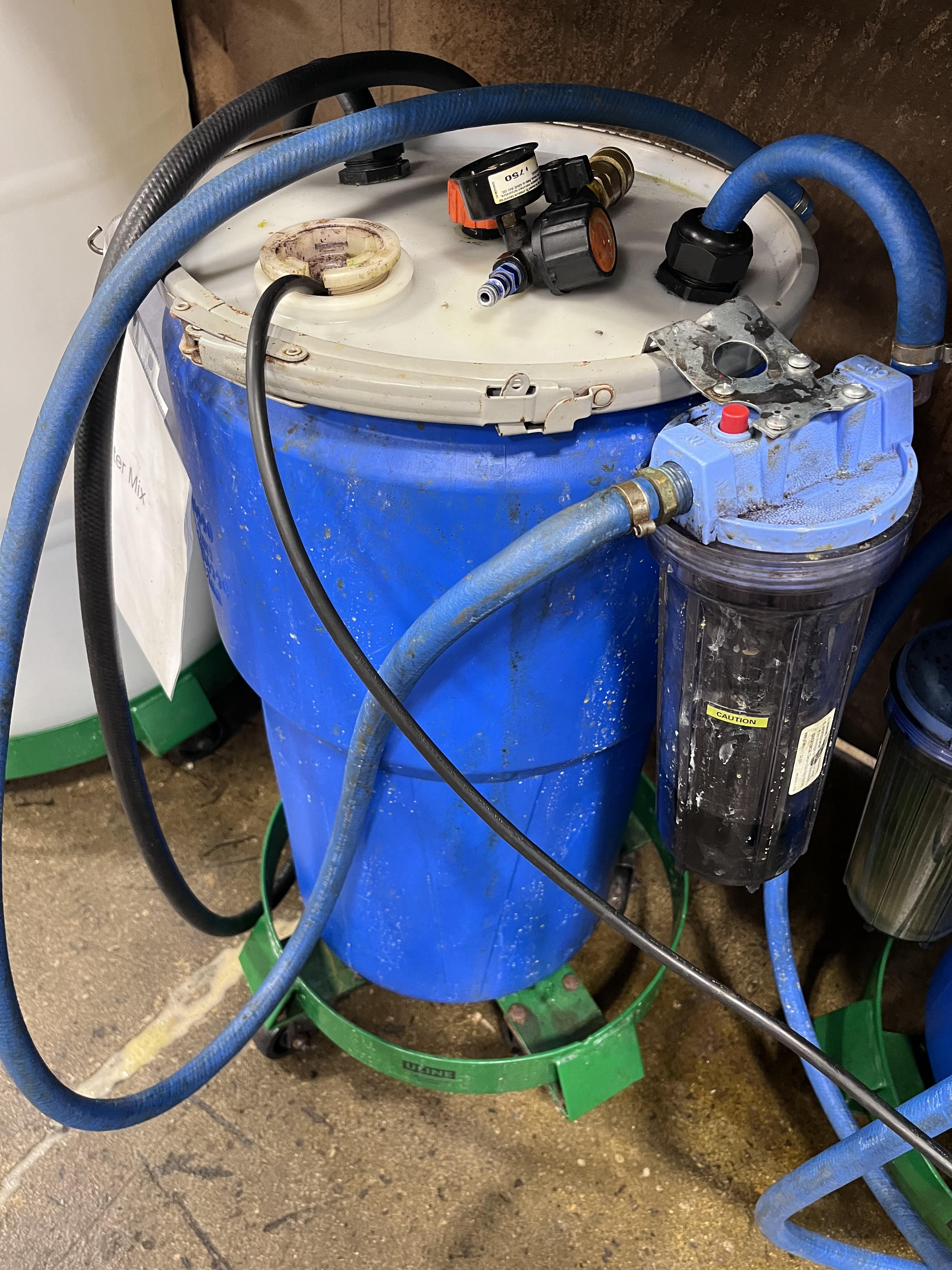
Connect the Rydlyme/Water Mix Supply Line to the Water Inlet on the unit.
Note
The Rydlyme/Water Mix Supply Line is the line coming out of the tank directly. This line is connected to a sump pump found at the bottom of the barrel and connects directly to the unit.
Run the sump pump of the Rydlyme/Water Mix tank by plugging in the power cord of the sump pump to an electrical outlet.
Let the sump pump run for 15 minutes.
Once the 15 minutes have elapsed, unplug the sump pump power cord. Unplug the Rydlyme/Water Mix Supply and Return Lines from the unit and reverse the connections.
Replug in the Rydlyme/Water Mix tank sump pump power cord to an electrical outlet and run the sump pump for additional 15 minutes.
Once the additional 15 minutes have elapsed, unplug the sump pump power cord and unplug the Rydlyme/Water Mix supply line from the Water Outlet port on the unit.
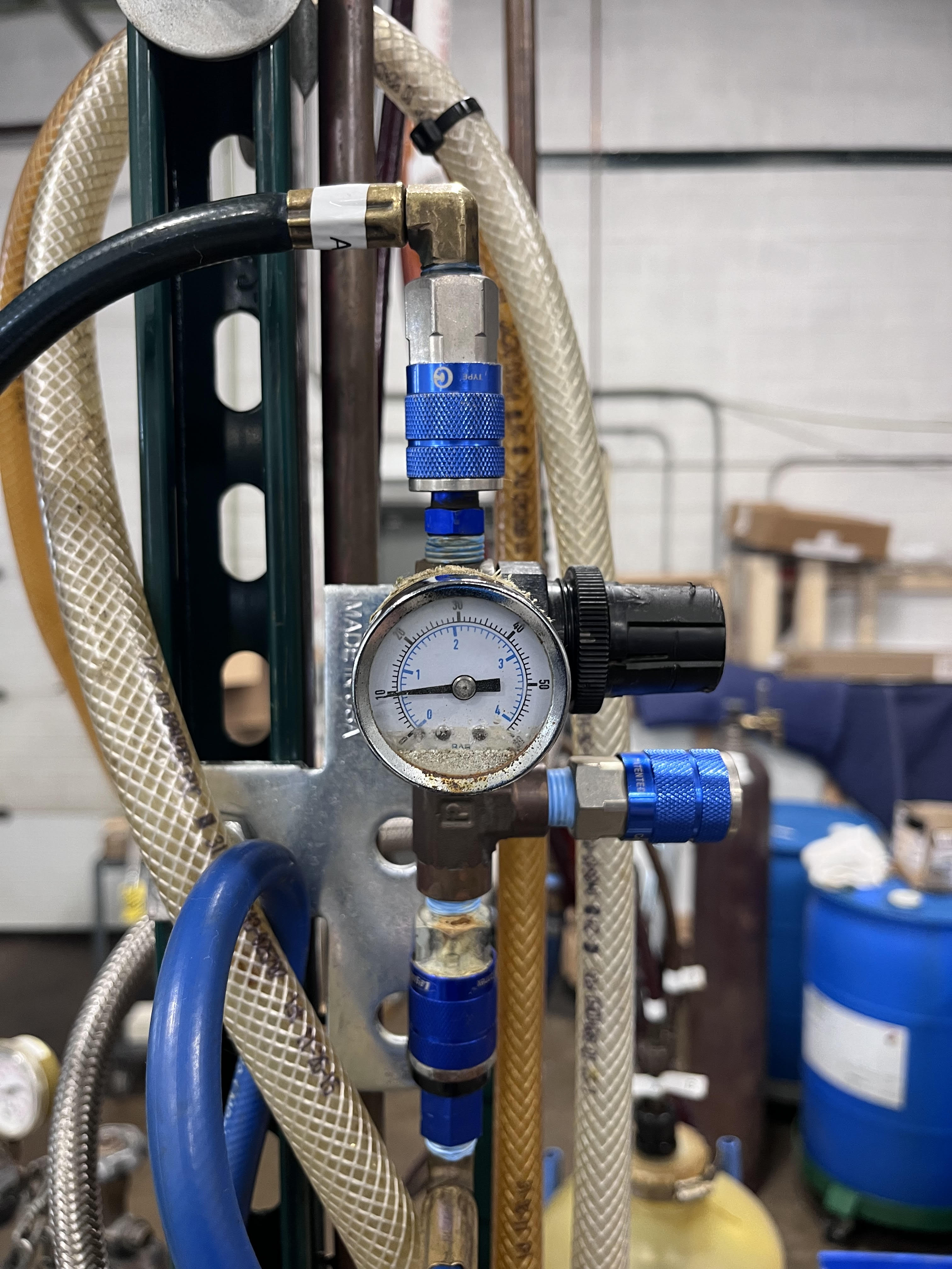
Obtain a standalone Pressure Regulator.

Make sure the Valve on the Pressure Regulator is in the closed position. Attach the Pressure Regulator to the Water Outlet Connector. Obtain a penumatic line and attach it to the Pressure Regulator. Slowly open the Pressure Regulator valve to blowout the acid from the unit. Keep blowing out acid until all the acid is drained out of the unit. Acid blowout should not be less than 3 minutes.
Note
Blowing out all the acid out of the unit is very important to prevent cross-contamination.
Once all the acid is drained out, close the Pressure Regulator Valve. Disconnect the Pressure Regulator and the Rydlyme/Water Mix Return Line. Unit is ready for Post-Descaling Water Flow.
Post-Descaling Water Flow
Post-Descaling is the process of measuring the water flow and water pressure in the unit after the Acid Wash is done. This will help to determine if there will be any improvement in water flow and water pressure post the Acid Wash process.
Repeat the steps in the water flushing process outlined in the Connect to city water and record the results.