GE LCC
Area Prep
A path for the magnet must be cleared and cleaned. The floor must be swept in the event that skates need to be used to move the magnet.
Connecting the Compressor
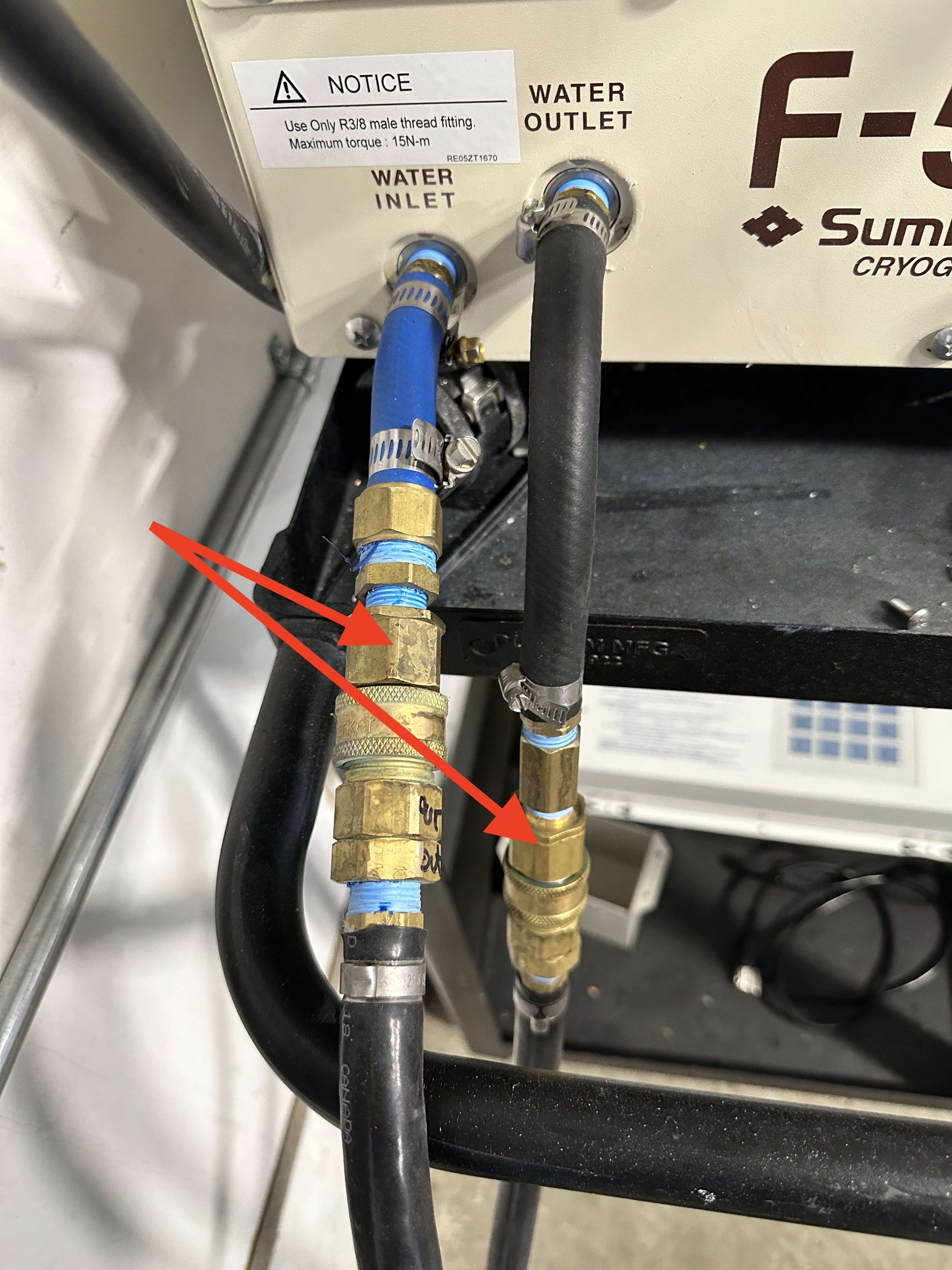
Prepare the helium compressor by connecting th water fittings.
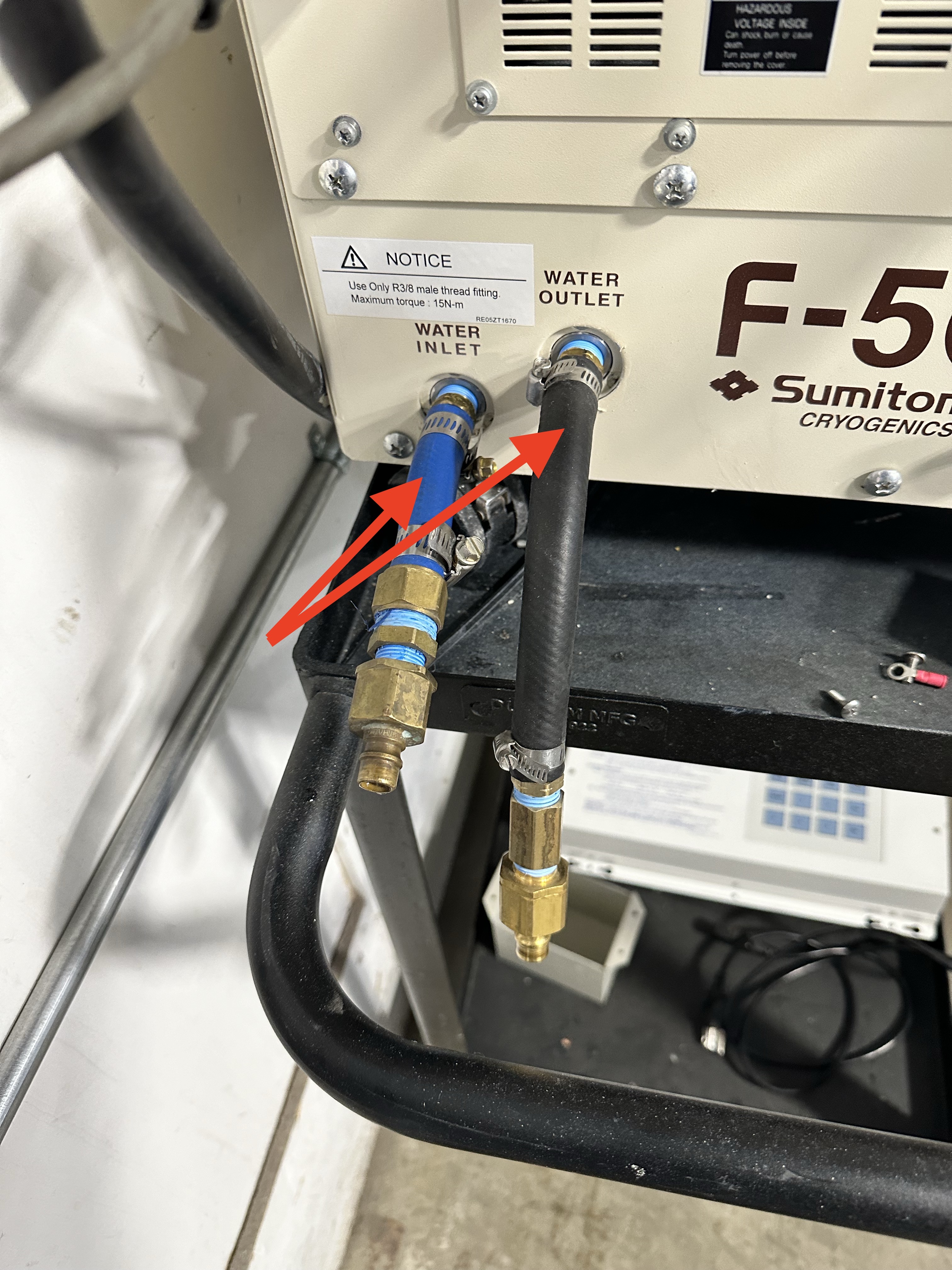
Connect the supply and return coolant lines.
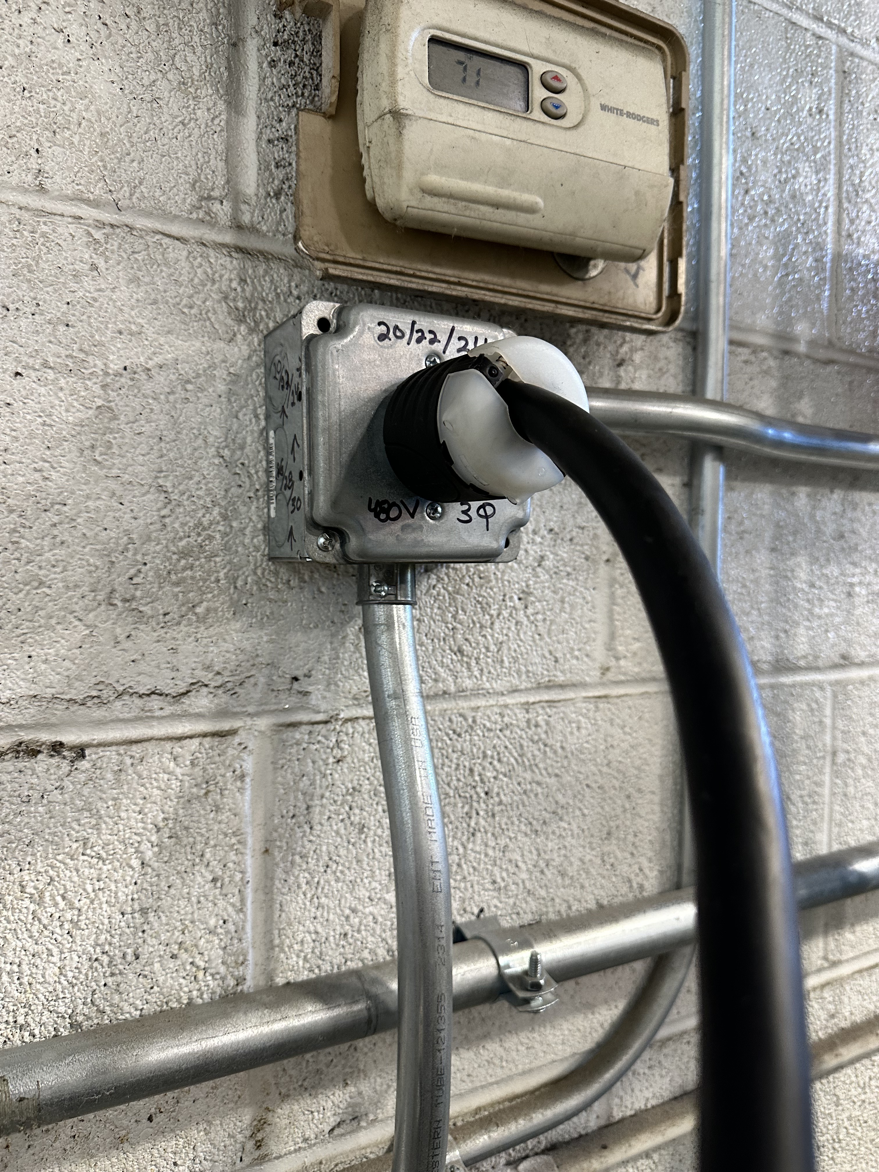
Danger
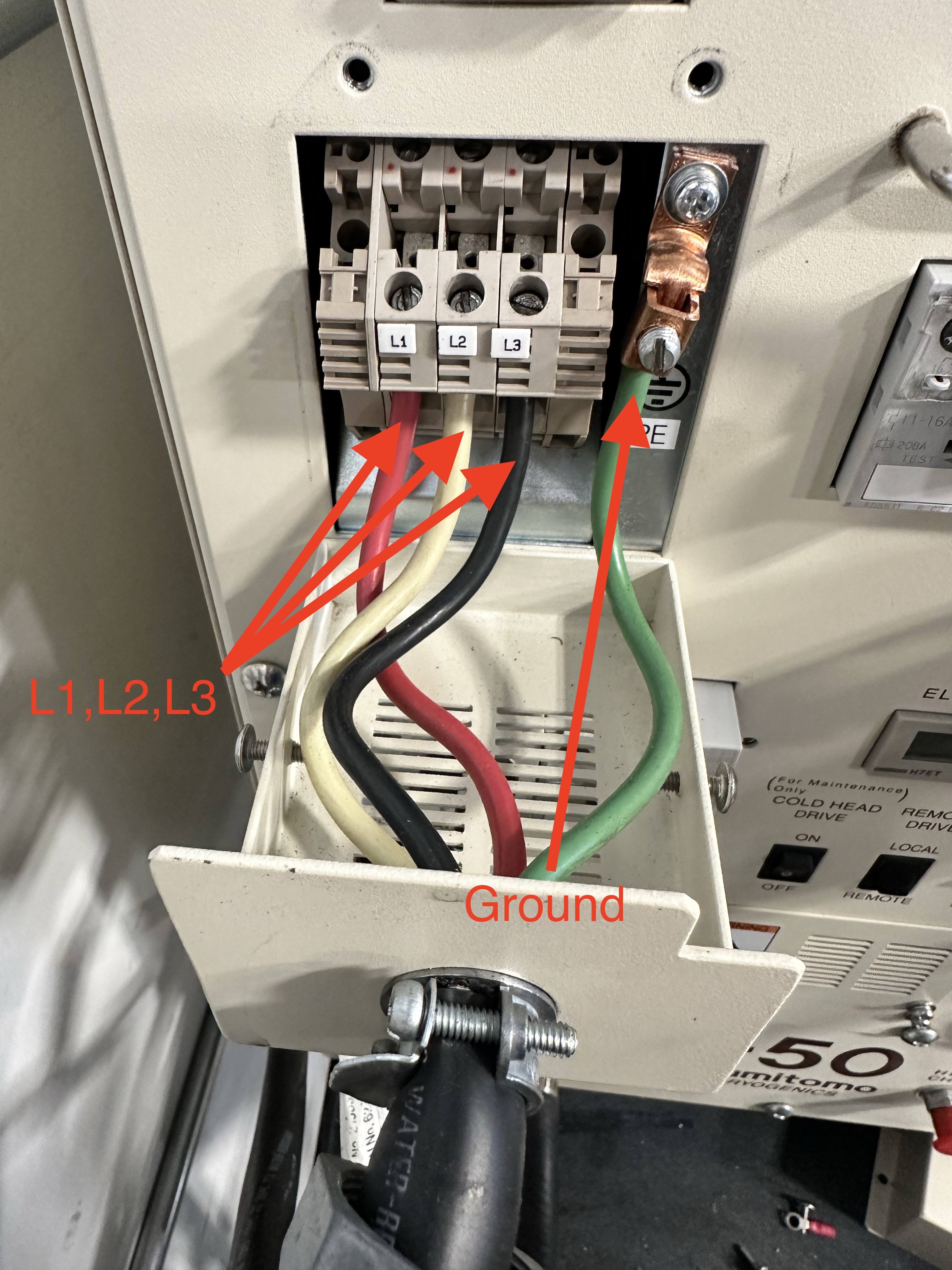
CONNECTING POWER REQUIRES WORKING WITH 480V POWER. USE CAUTION.
Danger
VERIFY THAT THE POWER PLUG IS NOT ENERGIZED.
Connect all three legs and the ground wires of the power cable to the helium compressor terminals.
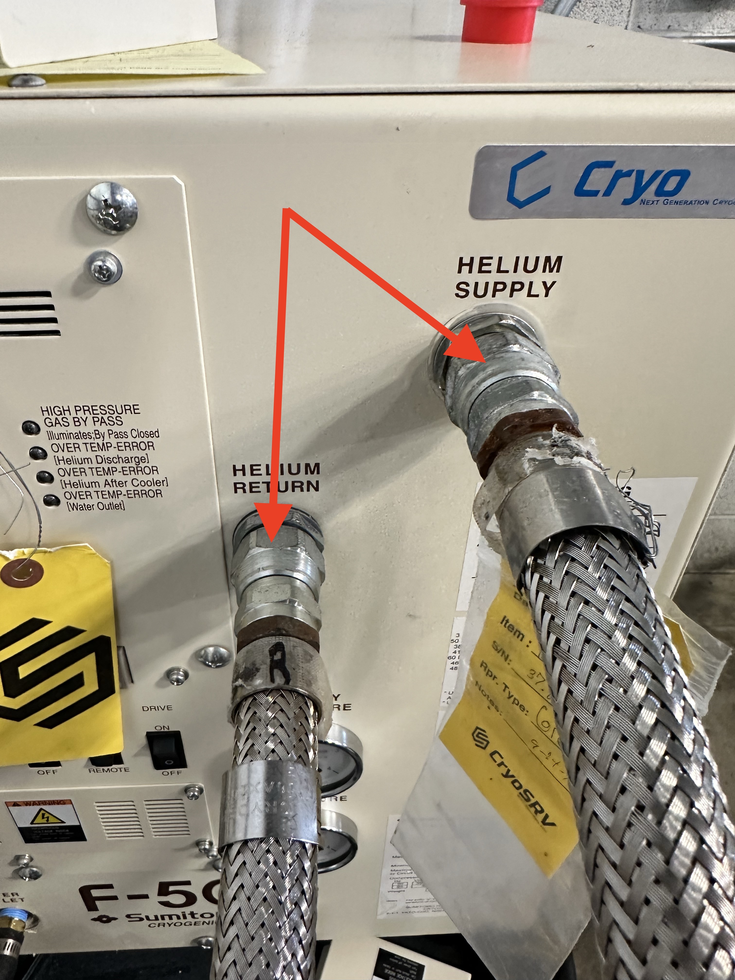
Connect the helium lines to the compressor.
Connect the drive cable to the compressor.
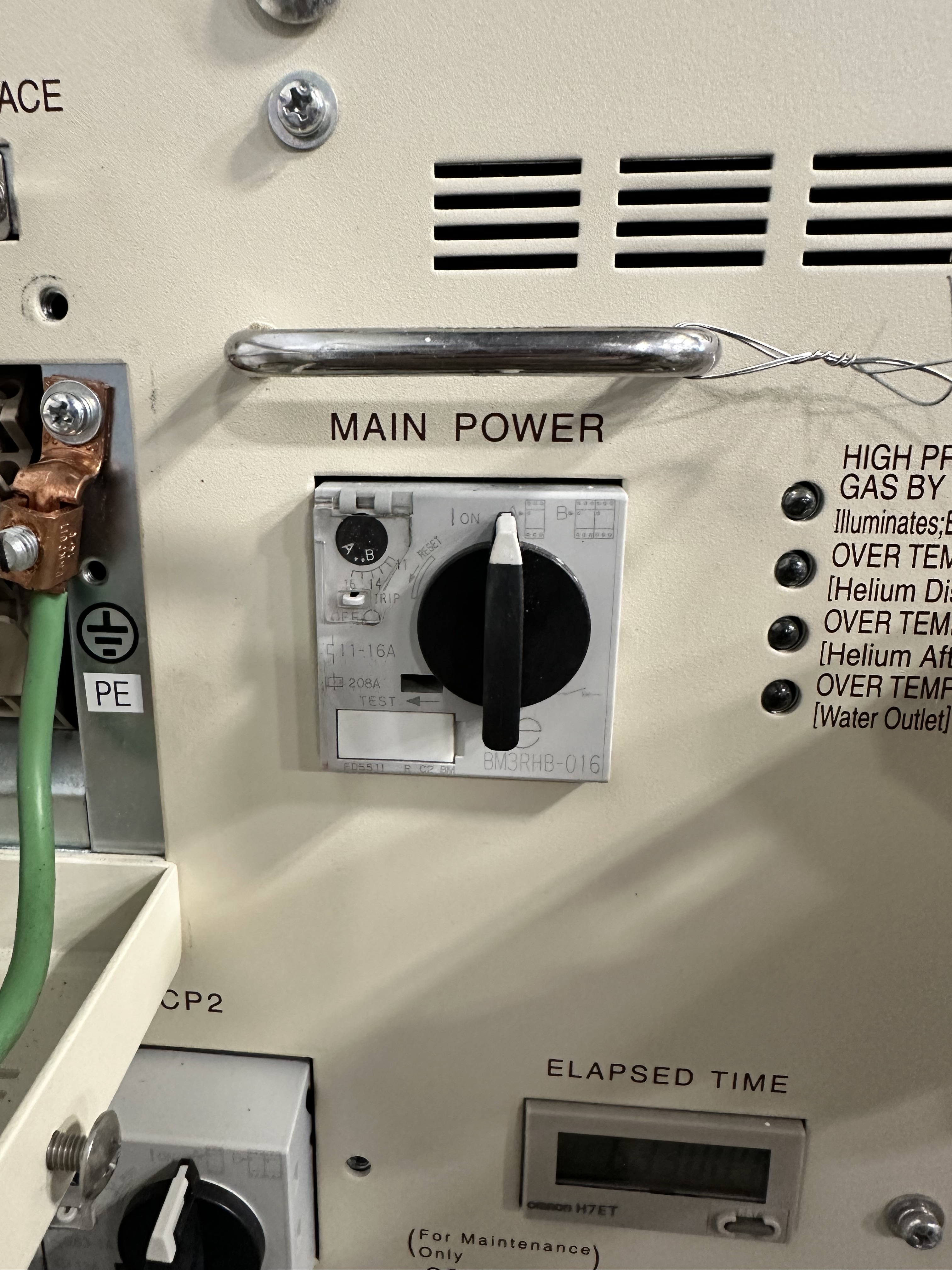
Verify the wires are secured to the terminals then plug in the helium compressor power cable to the wall.
Magnet Orientation
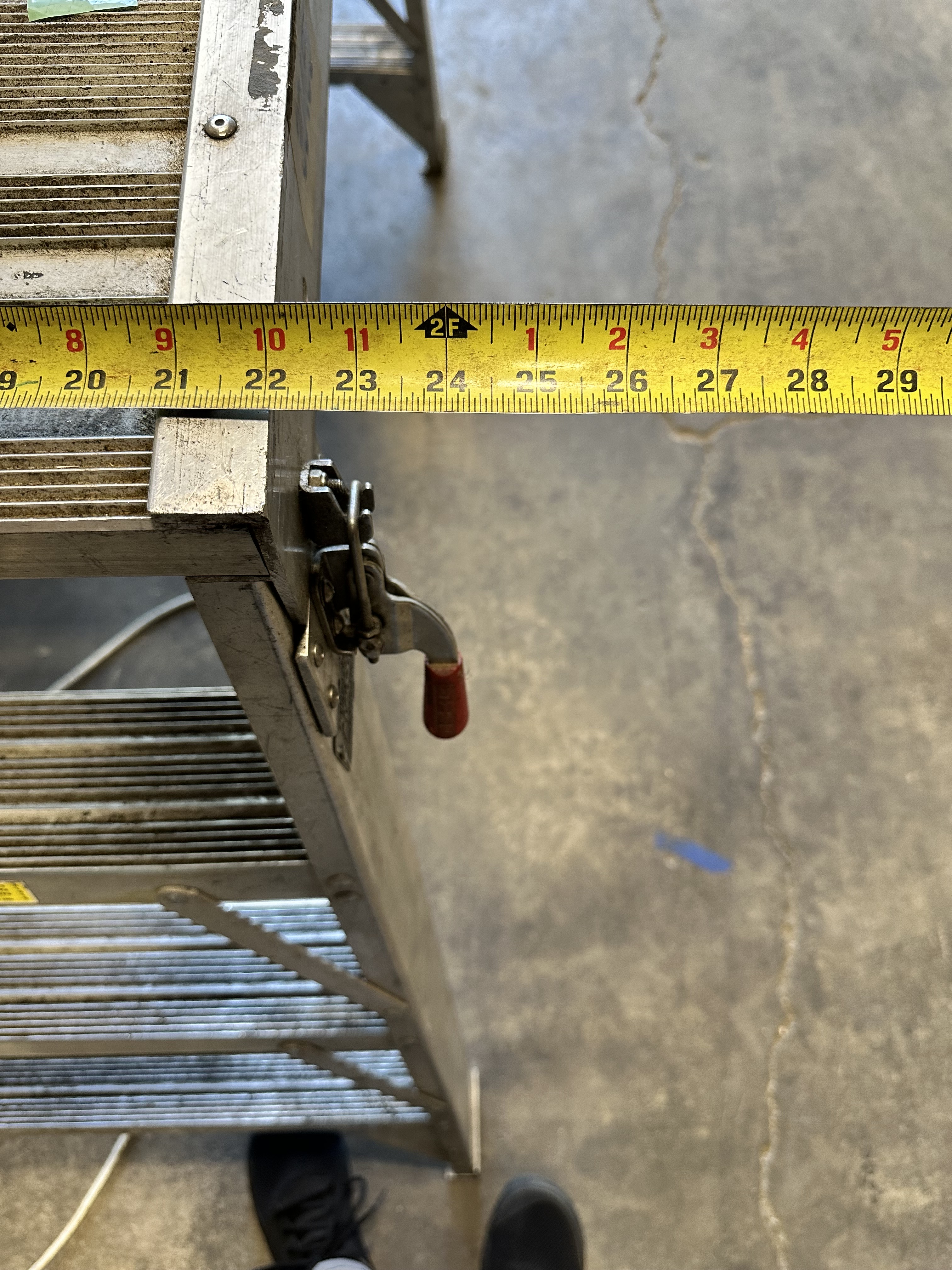
The service side of the magnet needs 25 inches of clearance in order to access the cold head and other instrumentation with the service platform. This must be communicated to the rigging team for proper placement.
Note
If possible, it is best to keep the service side of the magnet facing the aisle.
Connecting Life Support
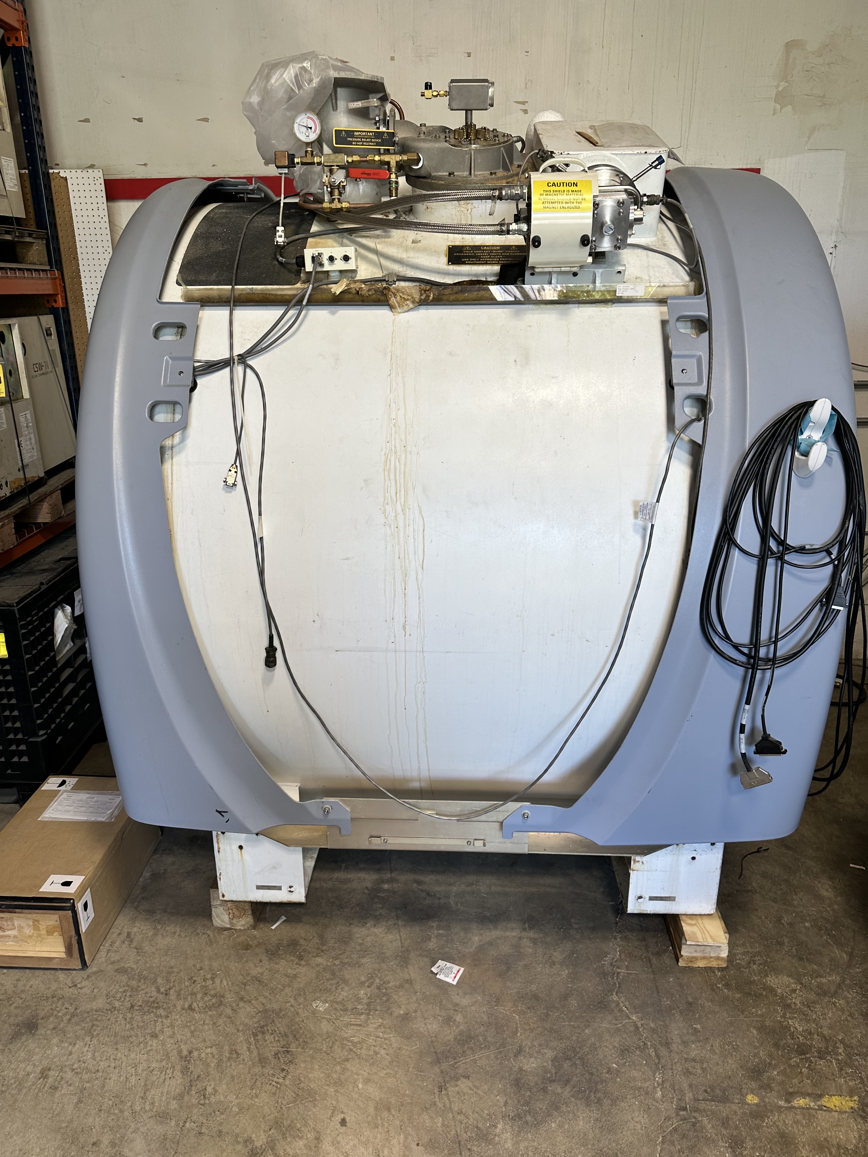
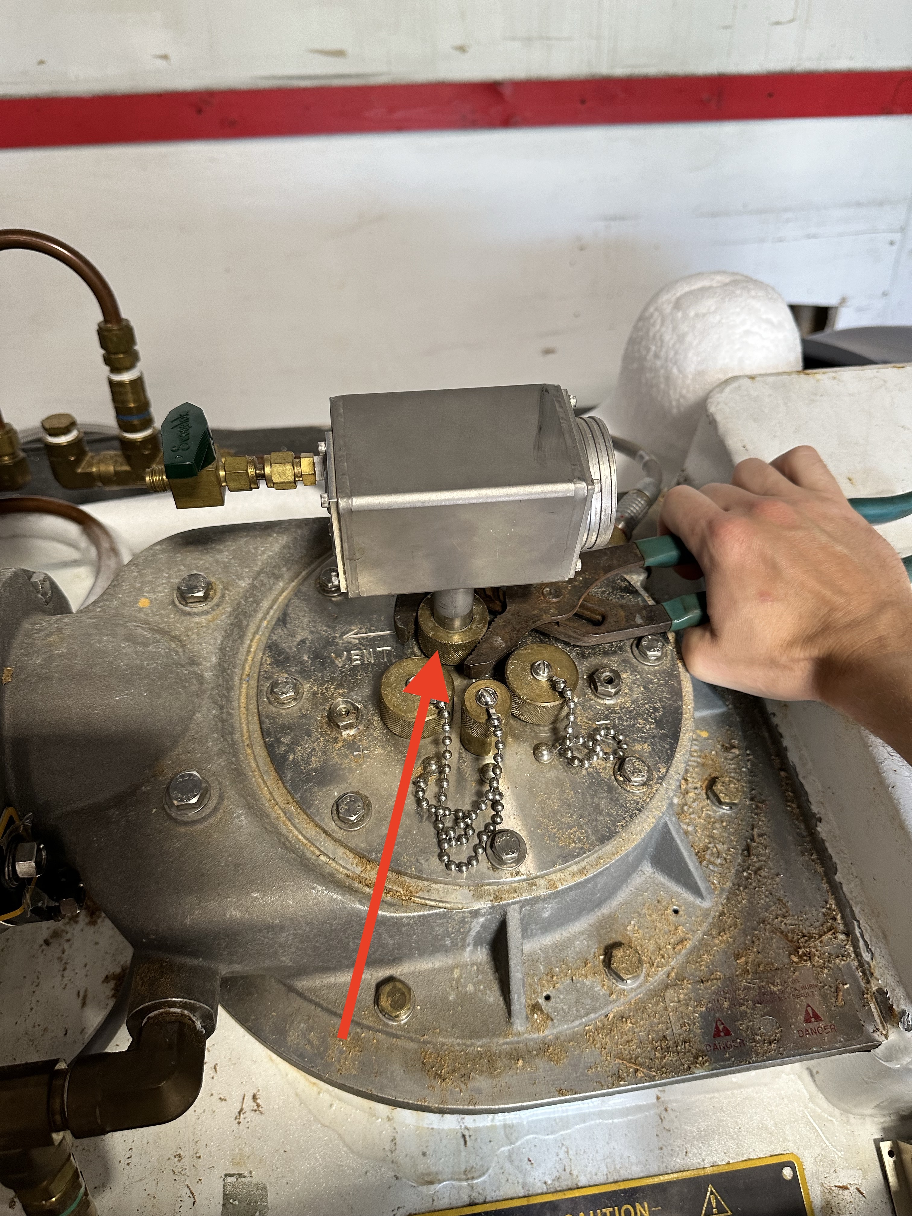
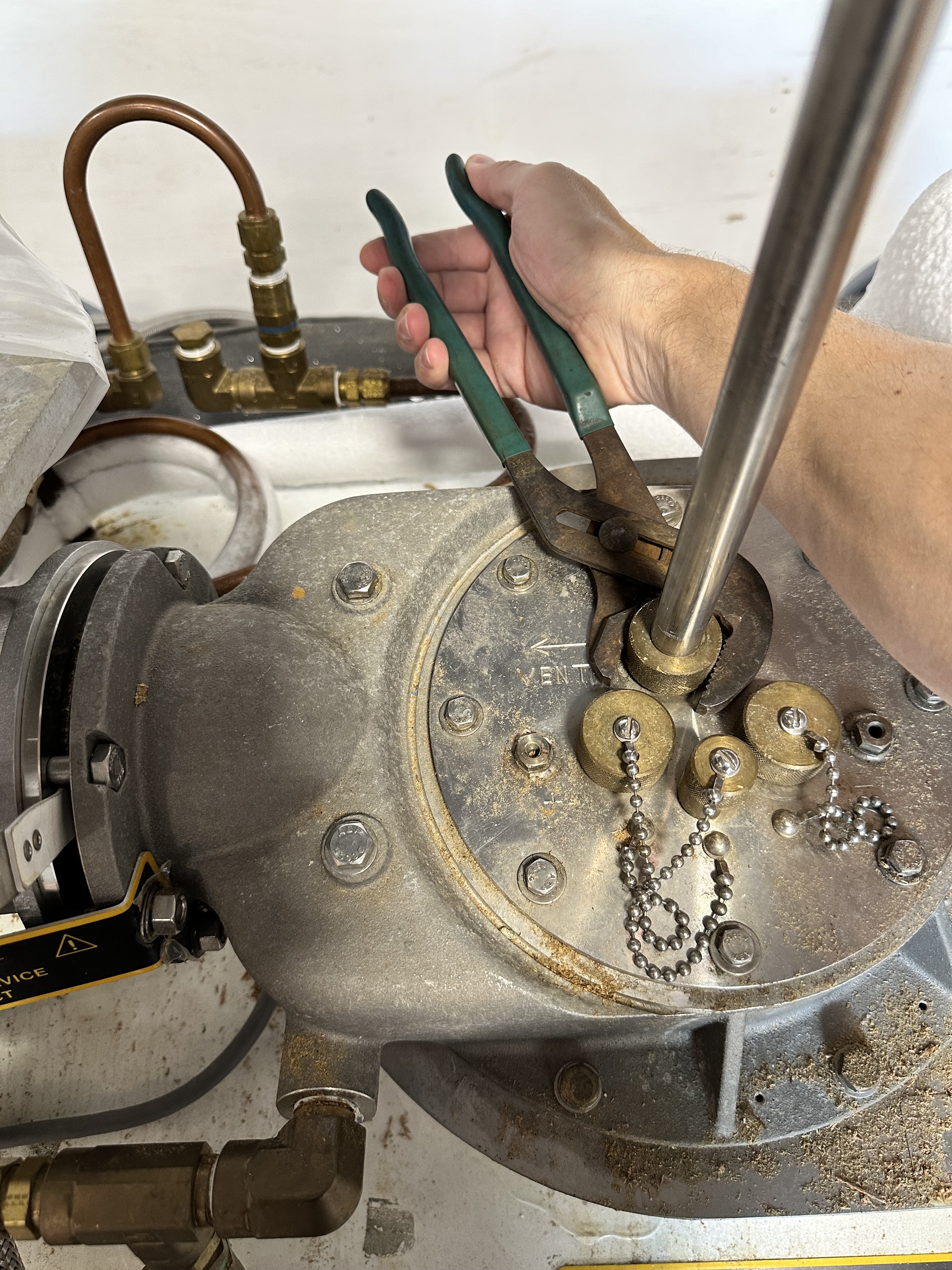
Lifting the Shim Lead
After the magnet is in position the supporting equipment must be connected and powered up. When the magnet arrives the shim-lead will be down and must be lifted in order to stabilize the pressure.
Danger
Cryogens can escape from the fitting during raising and lowering. Which can cause cryogen burns. Wear protective gloves.
Raise the shim lead to a height of 13 inches.
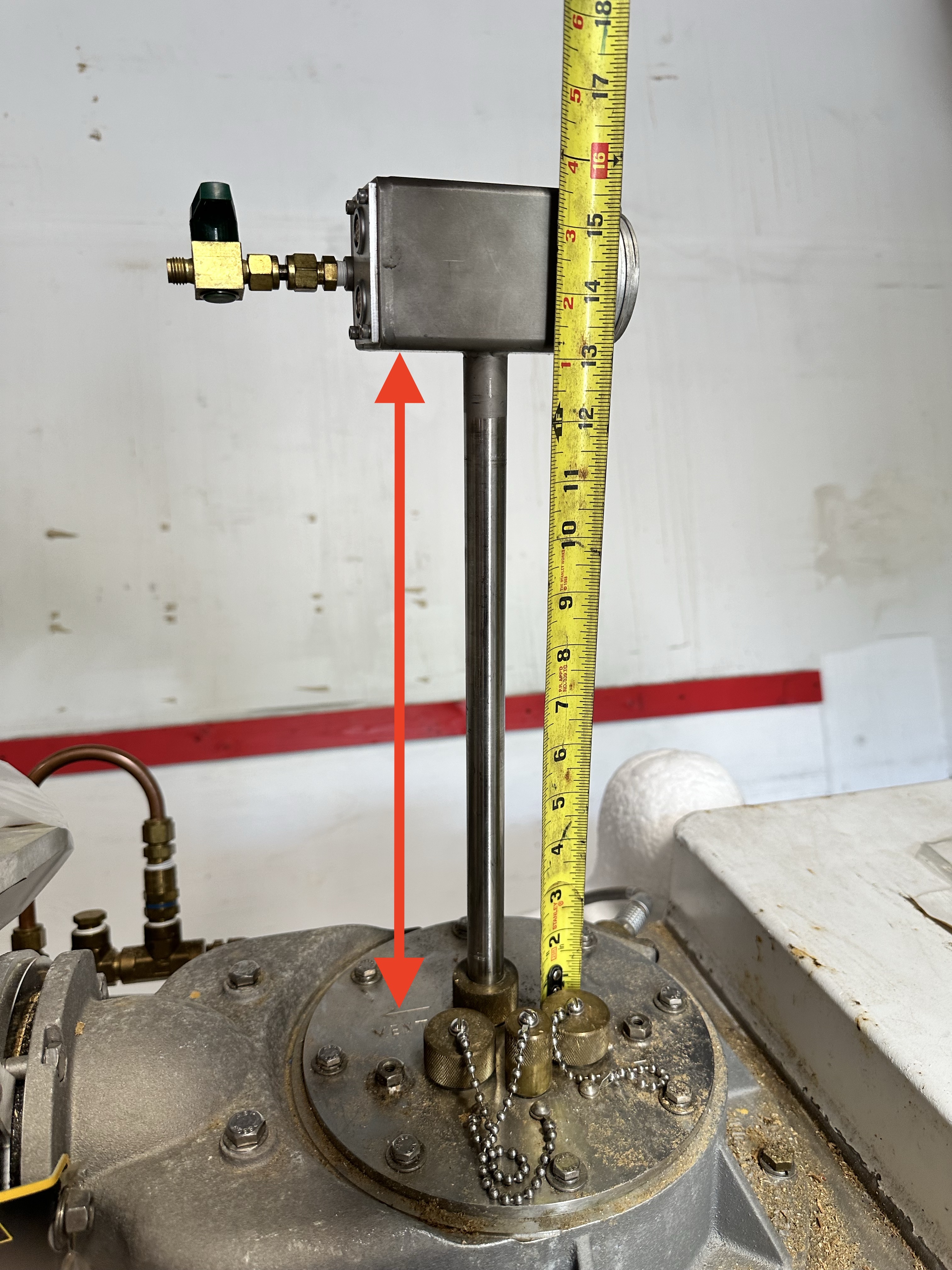
Once the shim lead is fully extended tighten down the compression nut to hold it in place.
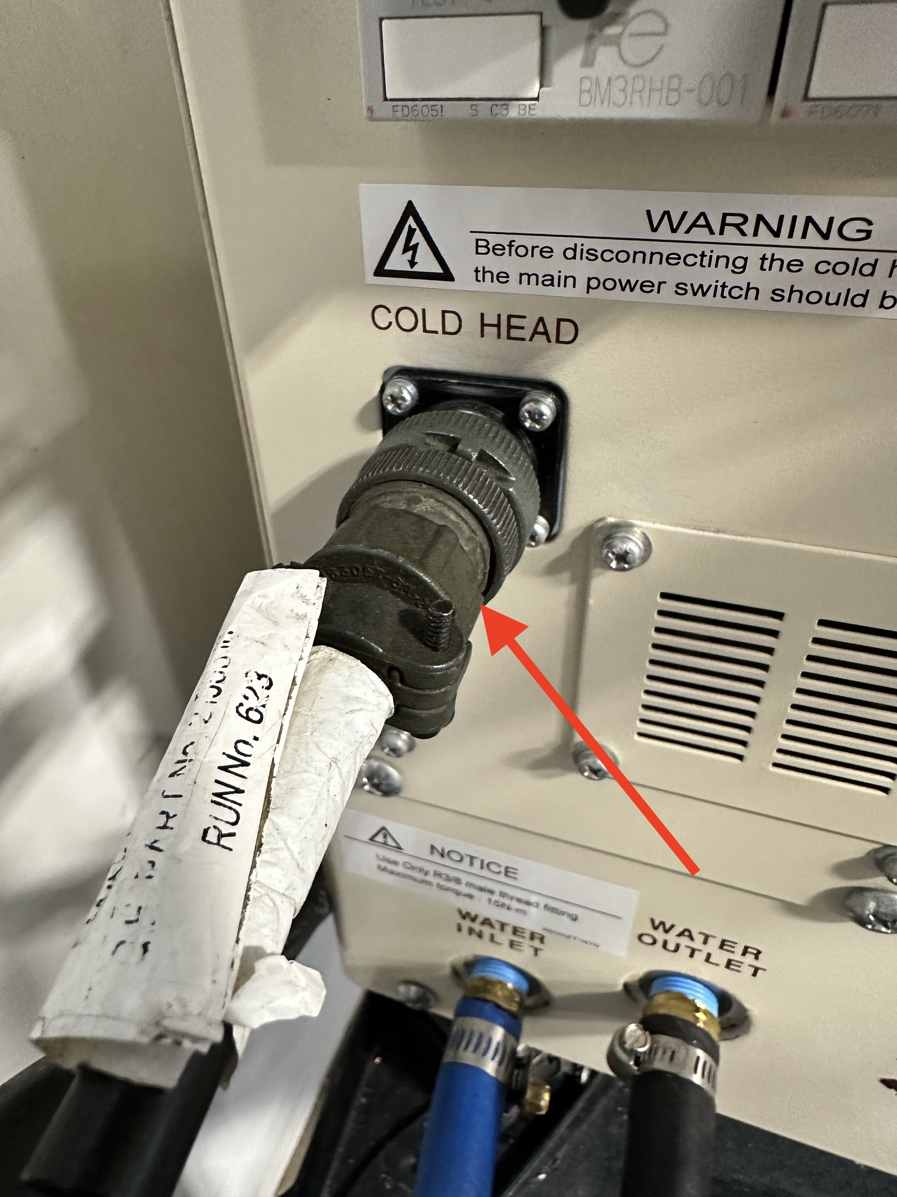
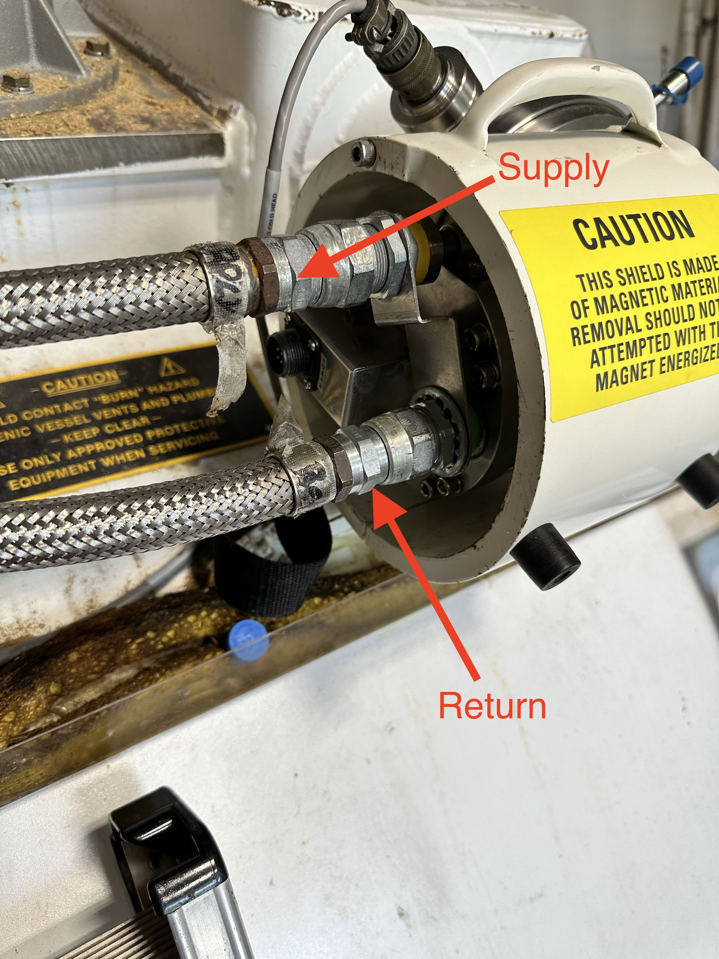
Connecting the Cold Head
Connect the helium lines to the cold head from the helium compressor.
Warning
Double check that the helium lines are connected correctly. Supply gas pumped directly into the motor will discharge the helium gas through the low pressure relief valve.
Connect the drive cable to the cold head from the helium compressor.
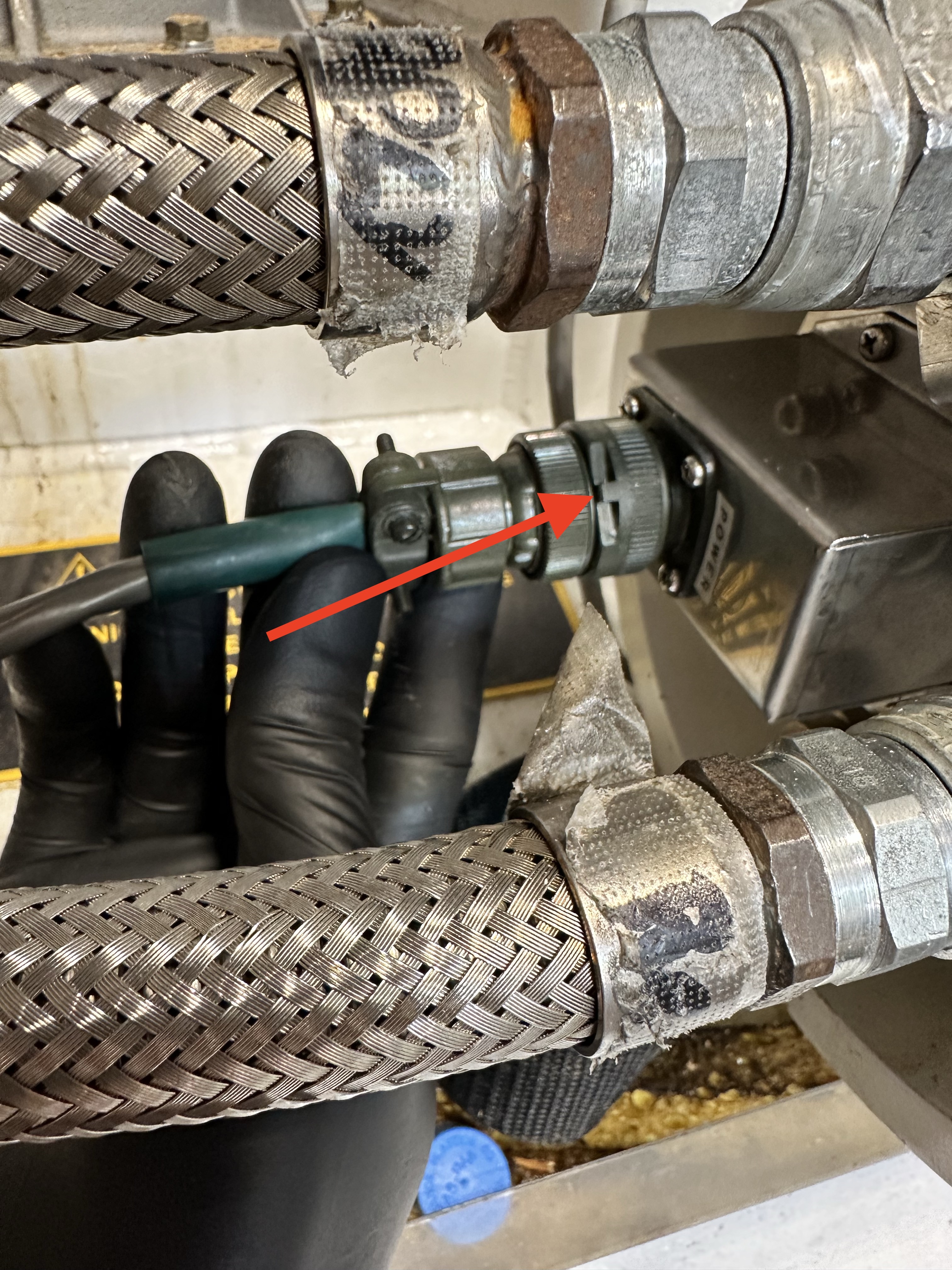
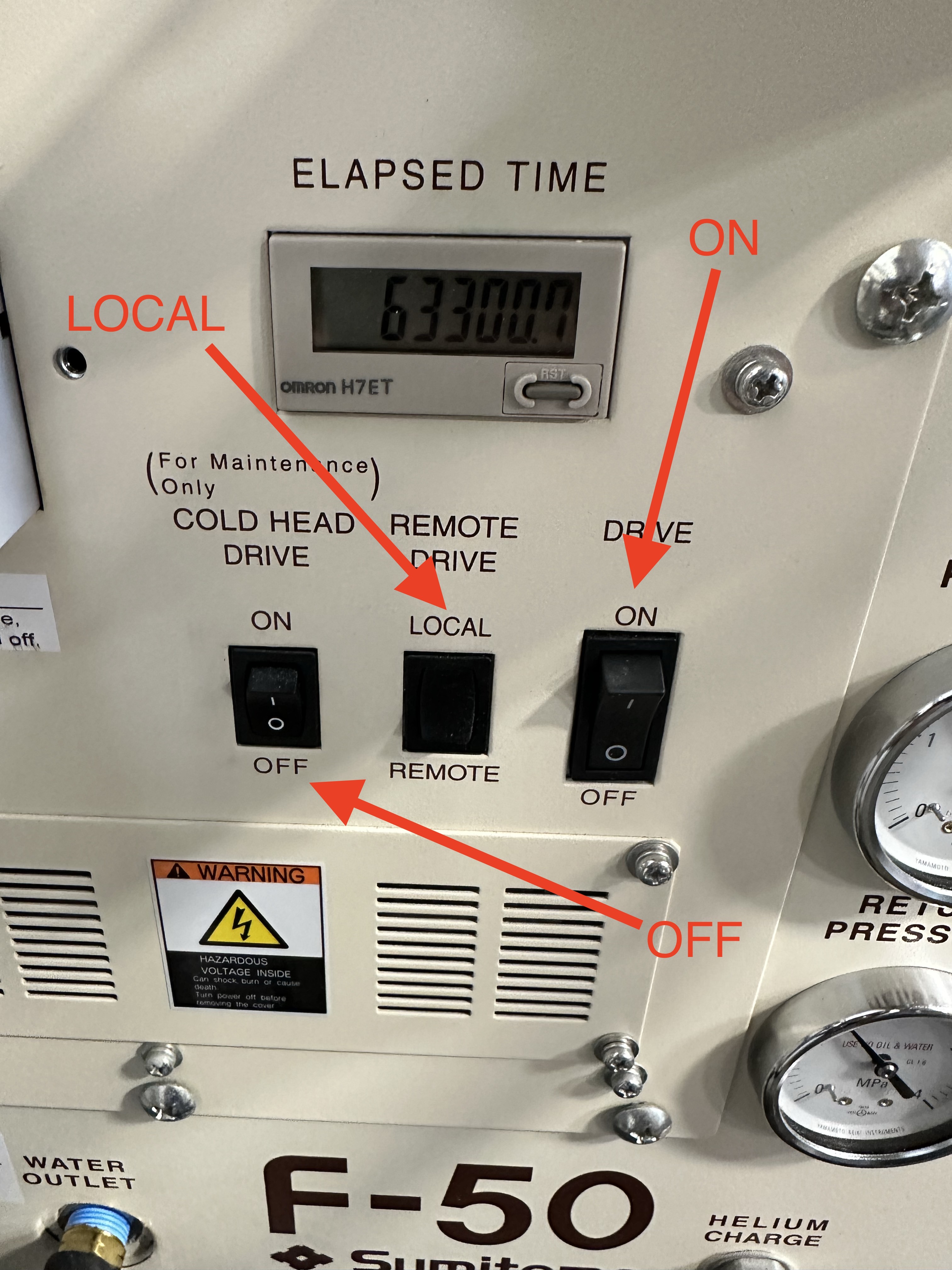
Power on the helium compressor to begin cooling.
Connecting Magnet Monitor
The MM3 has four cables that need to be connected to the magnet and helium compressor in order to capture all of the necessary data for monitoring.
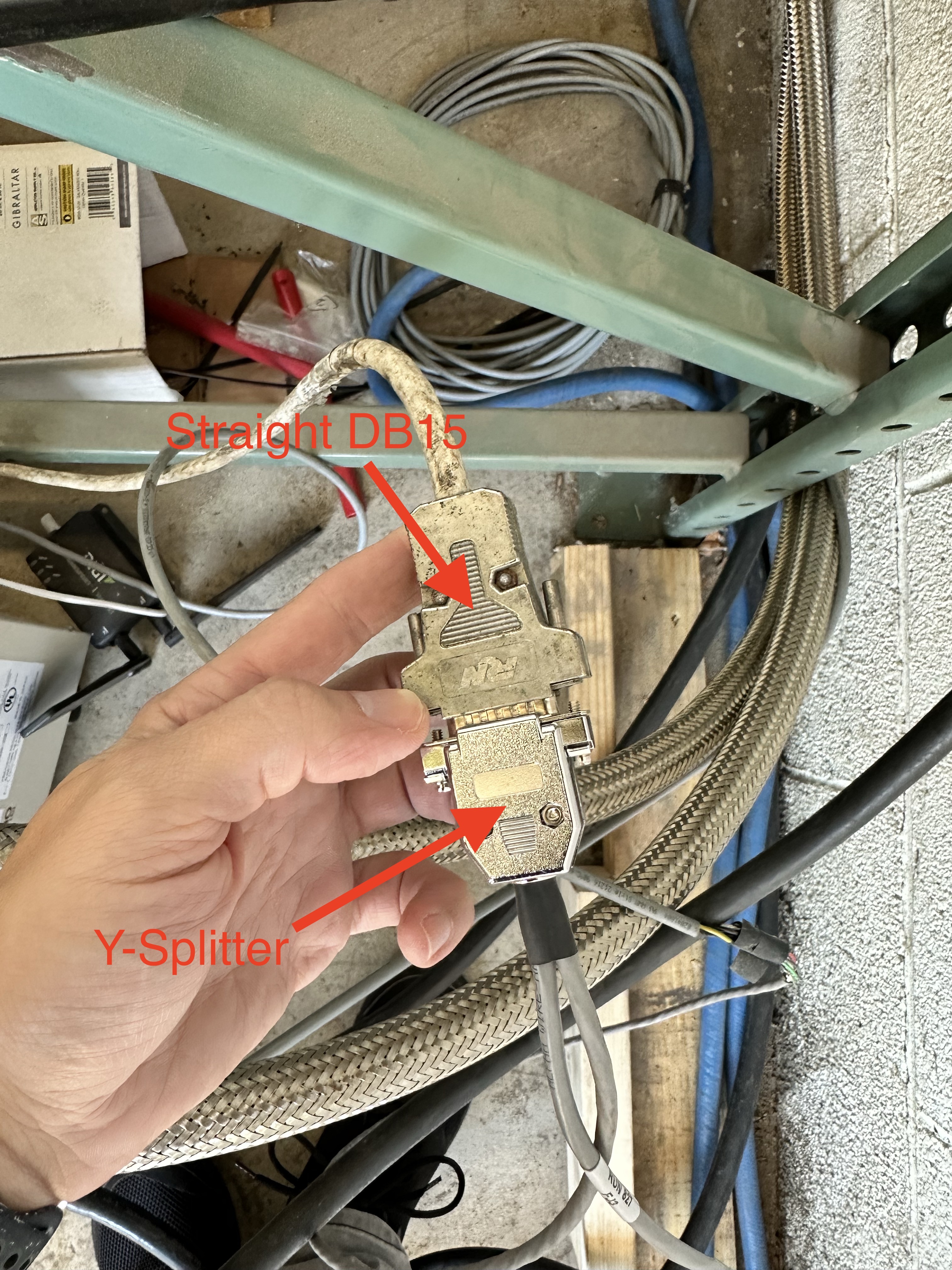
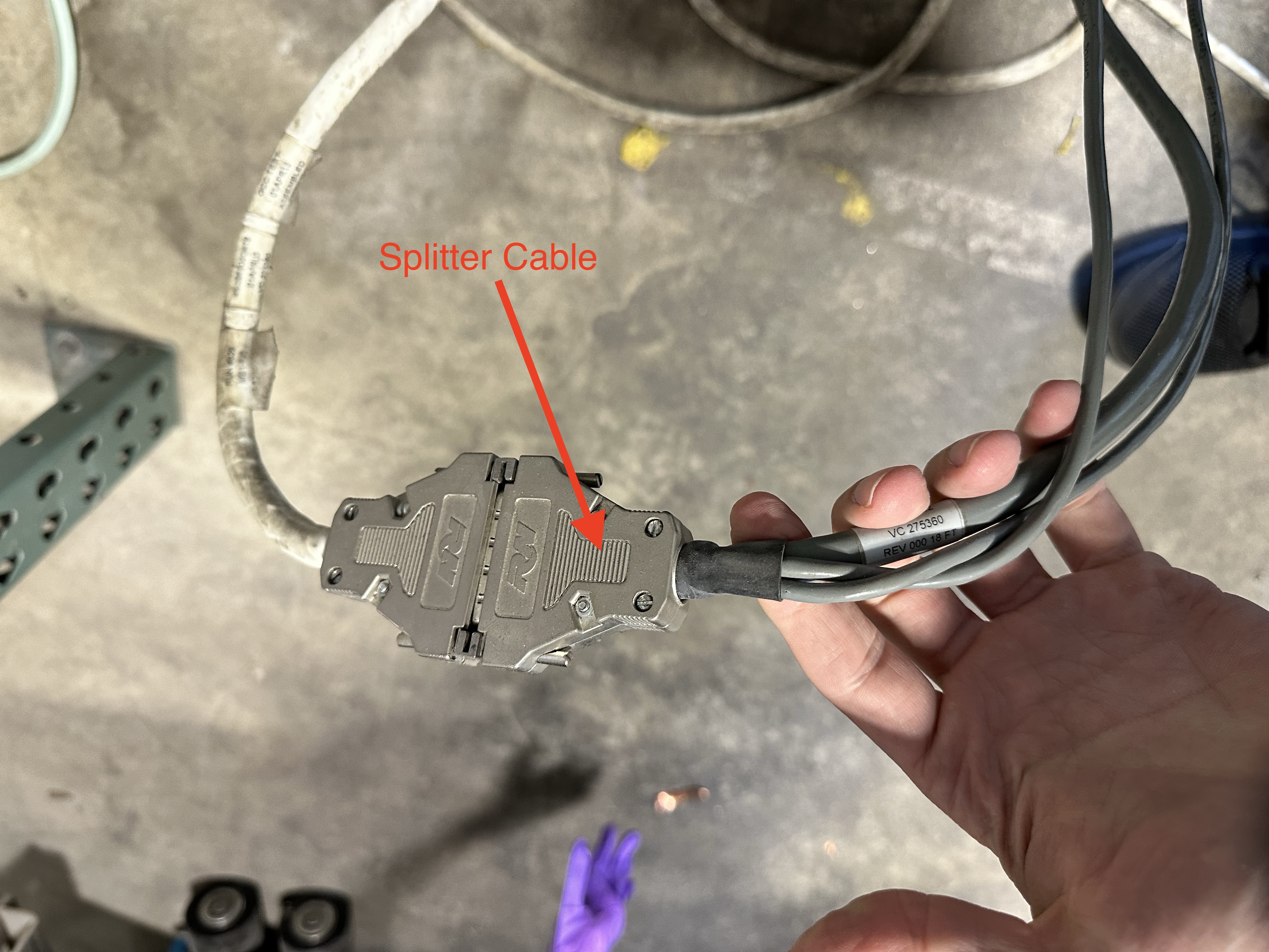
The helium compressor must be connected via Y splitter between the diagnostic interface and the flow meter.
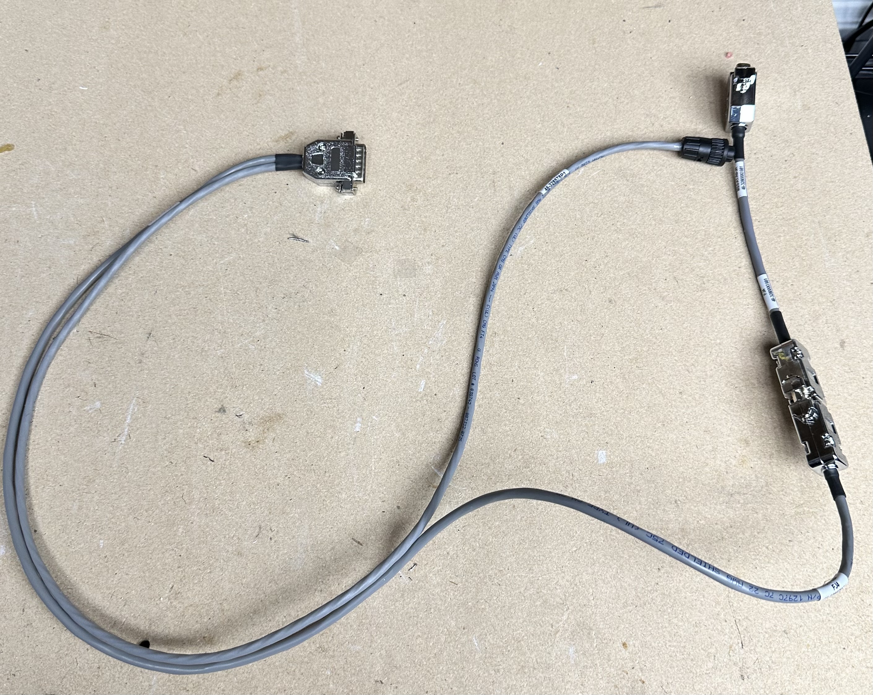
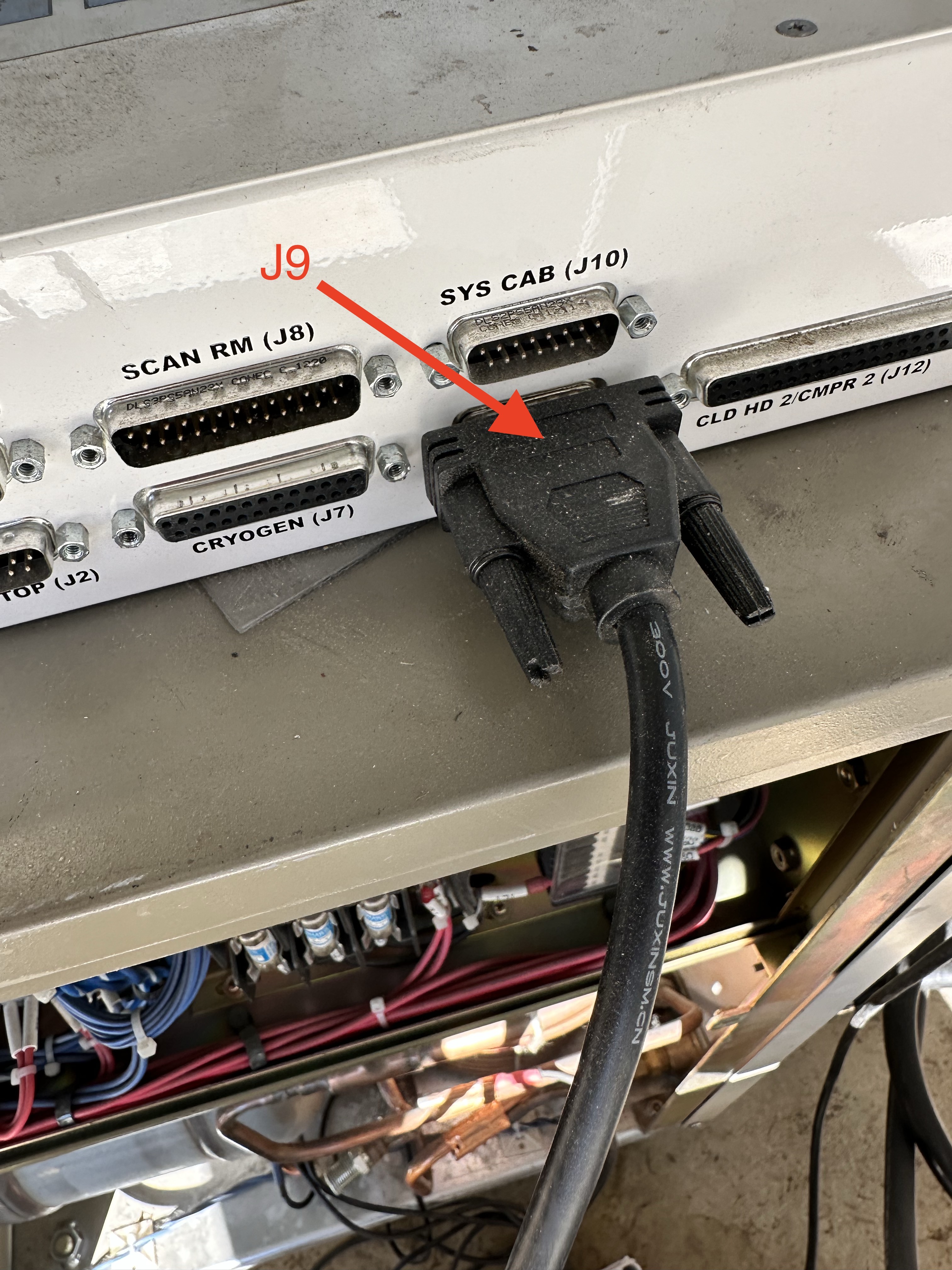
The Y splitter cable leads to a straight DB15 cable that connects to J9 on the MM3.
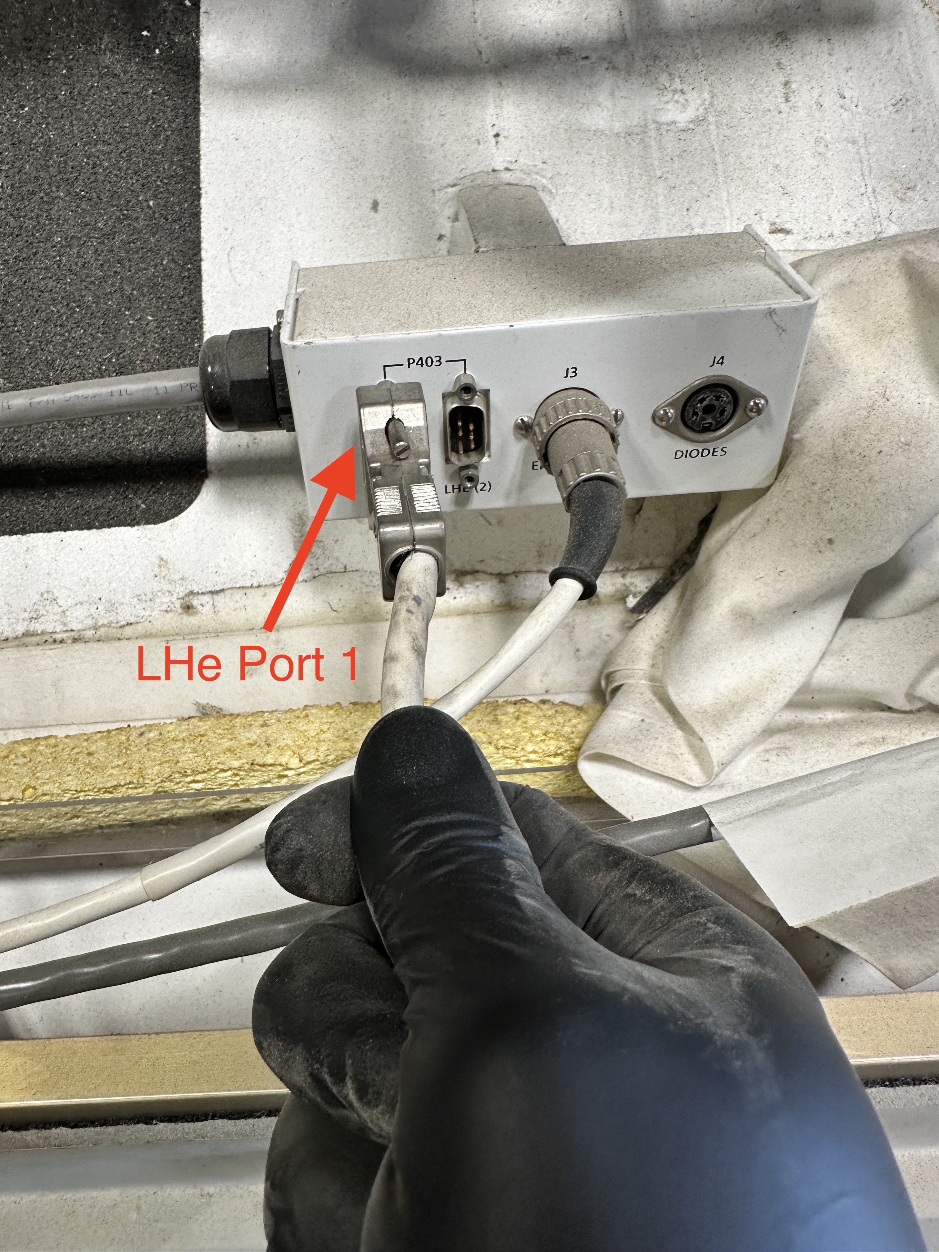
The J7 cable connects to the helium level port 1 or port 2 to the MM3.
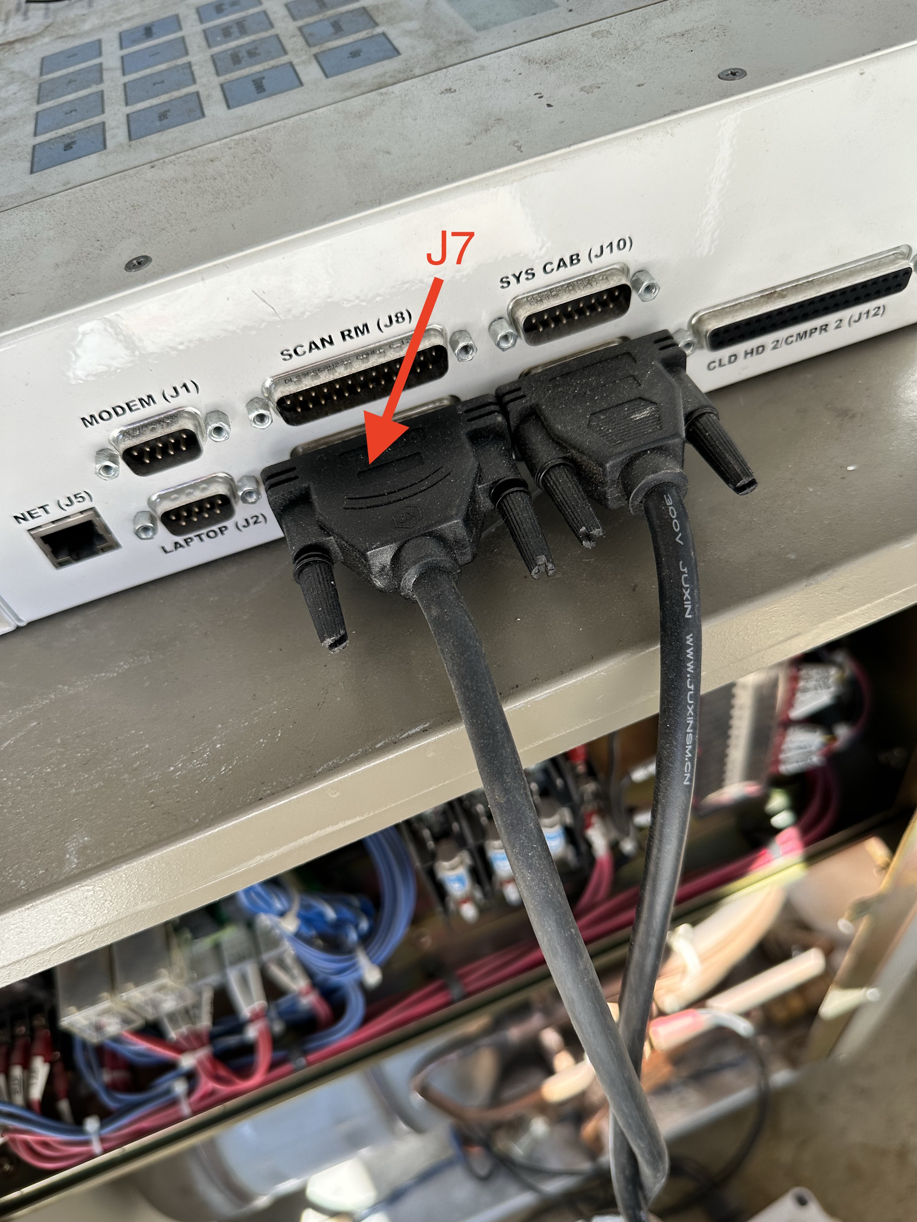
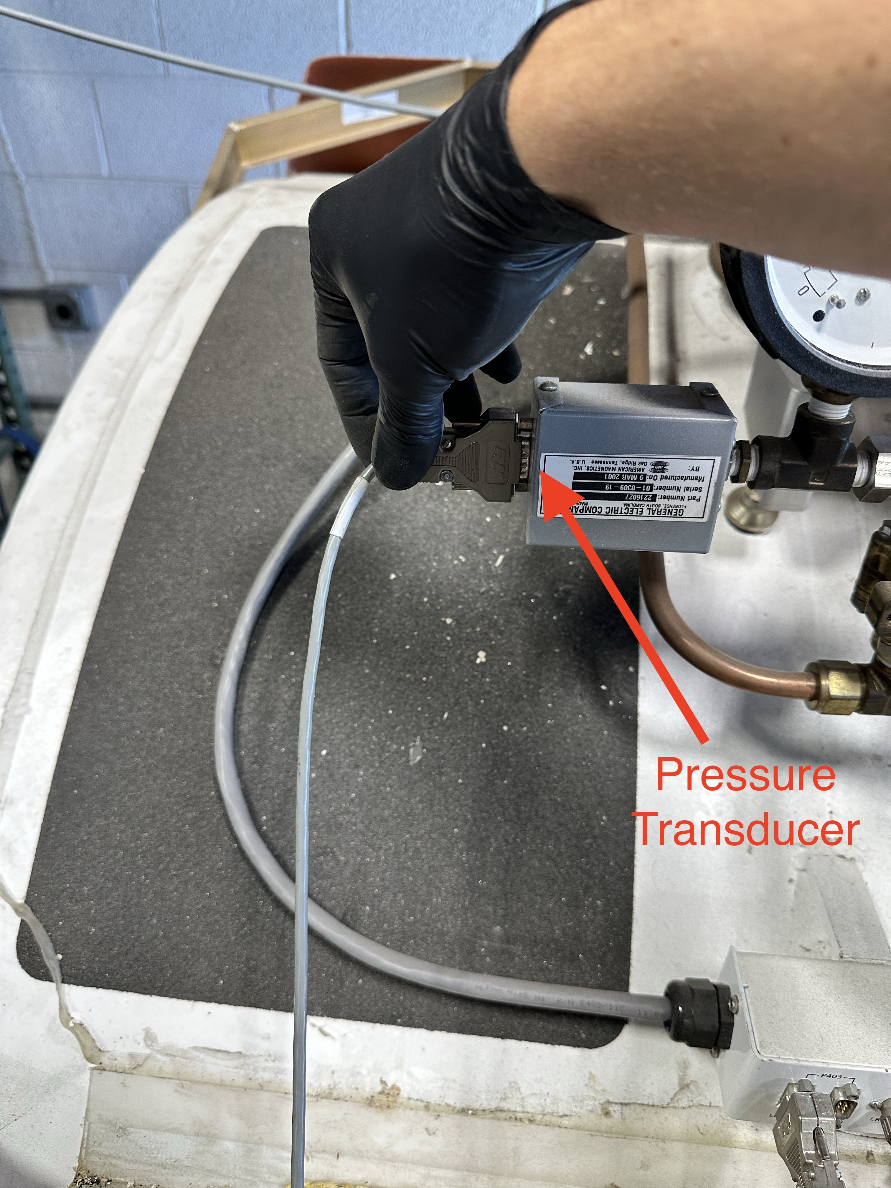
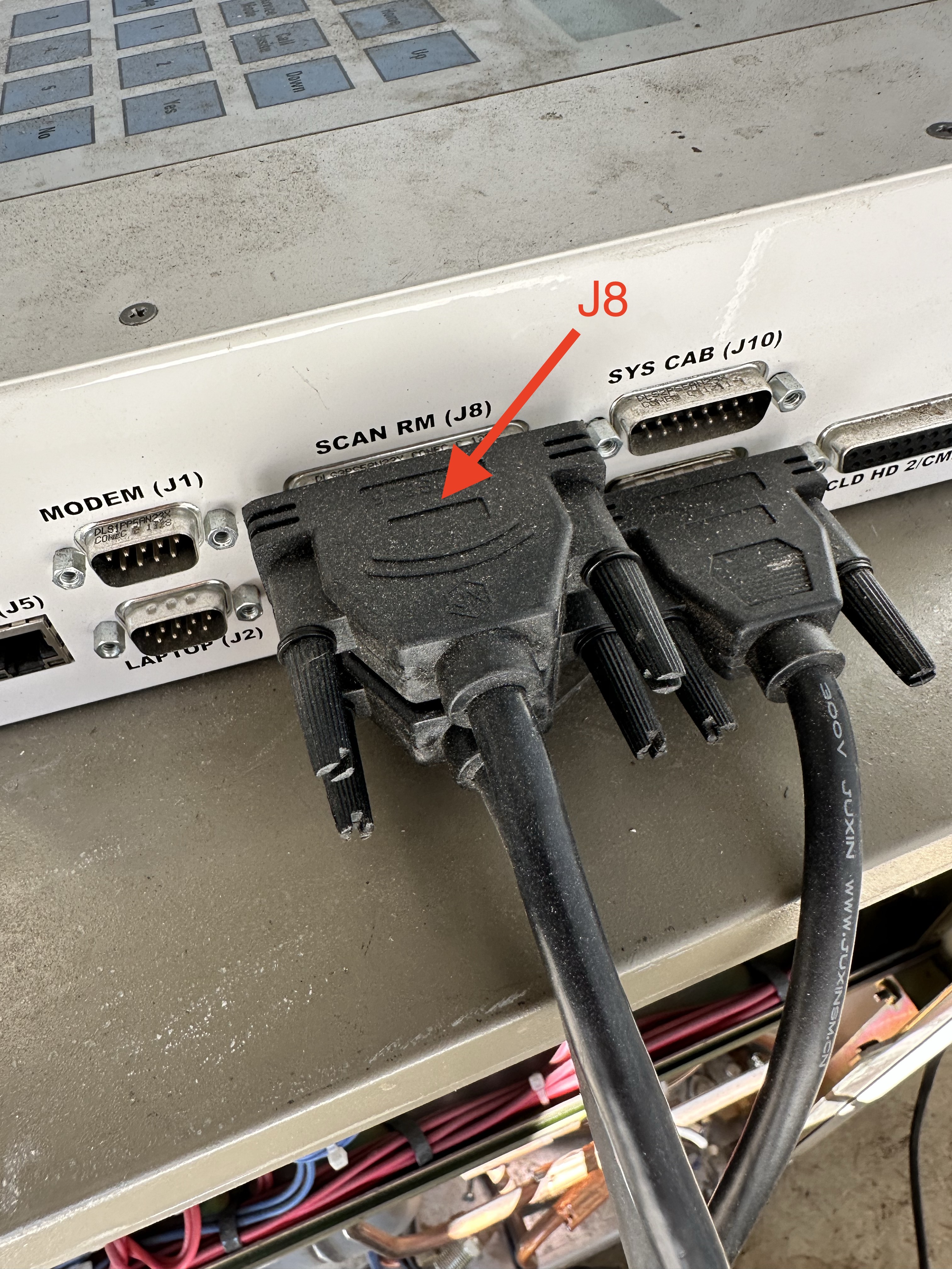
The J8 cable splits to the the pressure transducer as well as the magnet cold head temperature amplifier to the MM3.

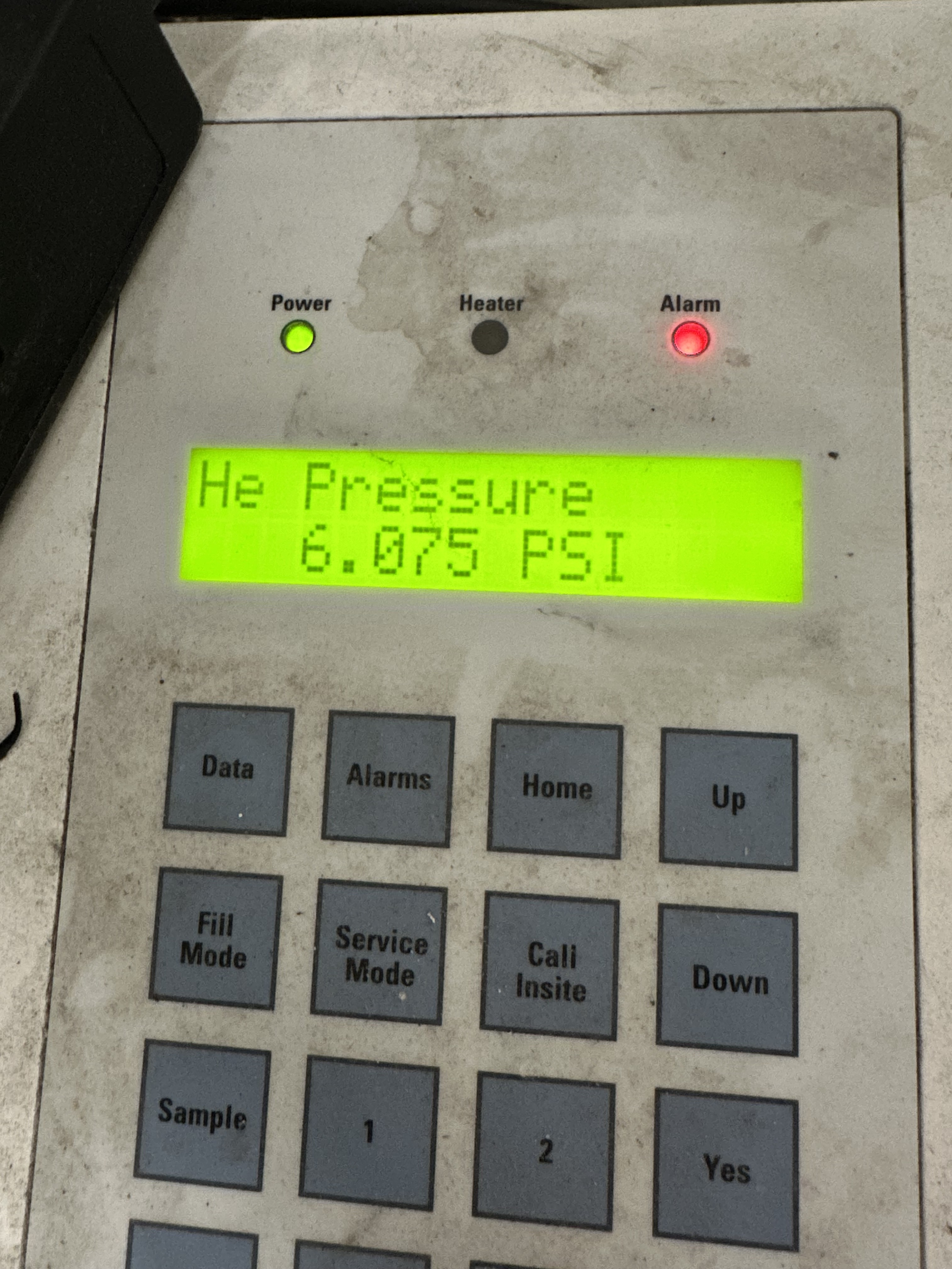
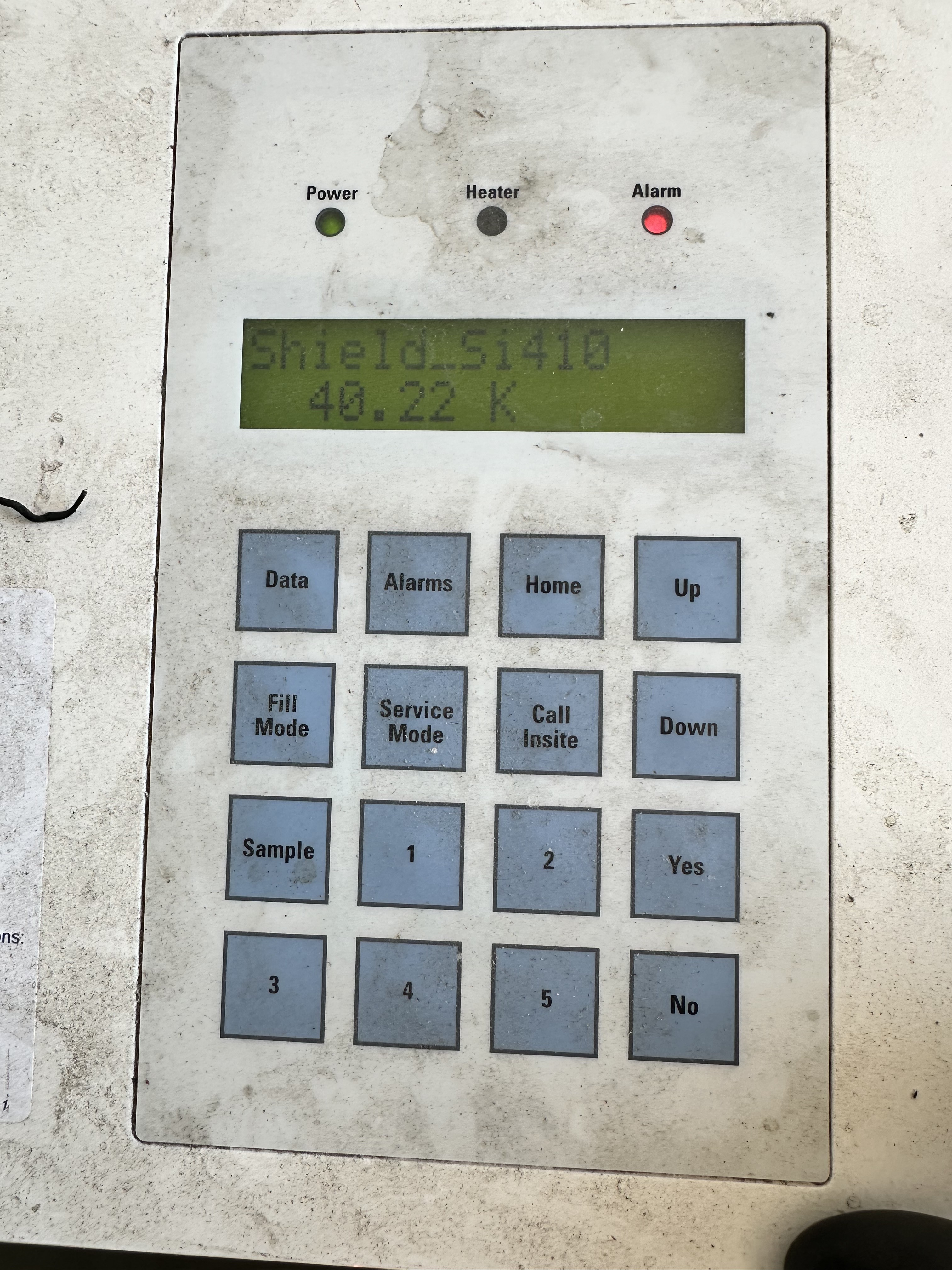
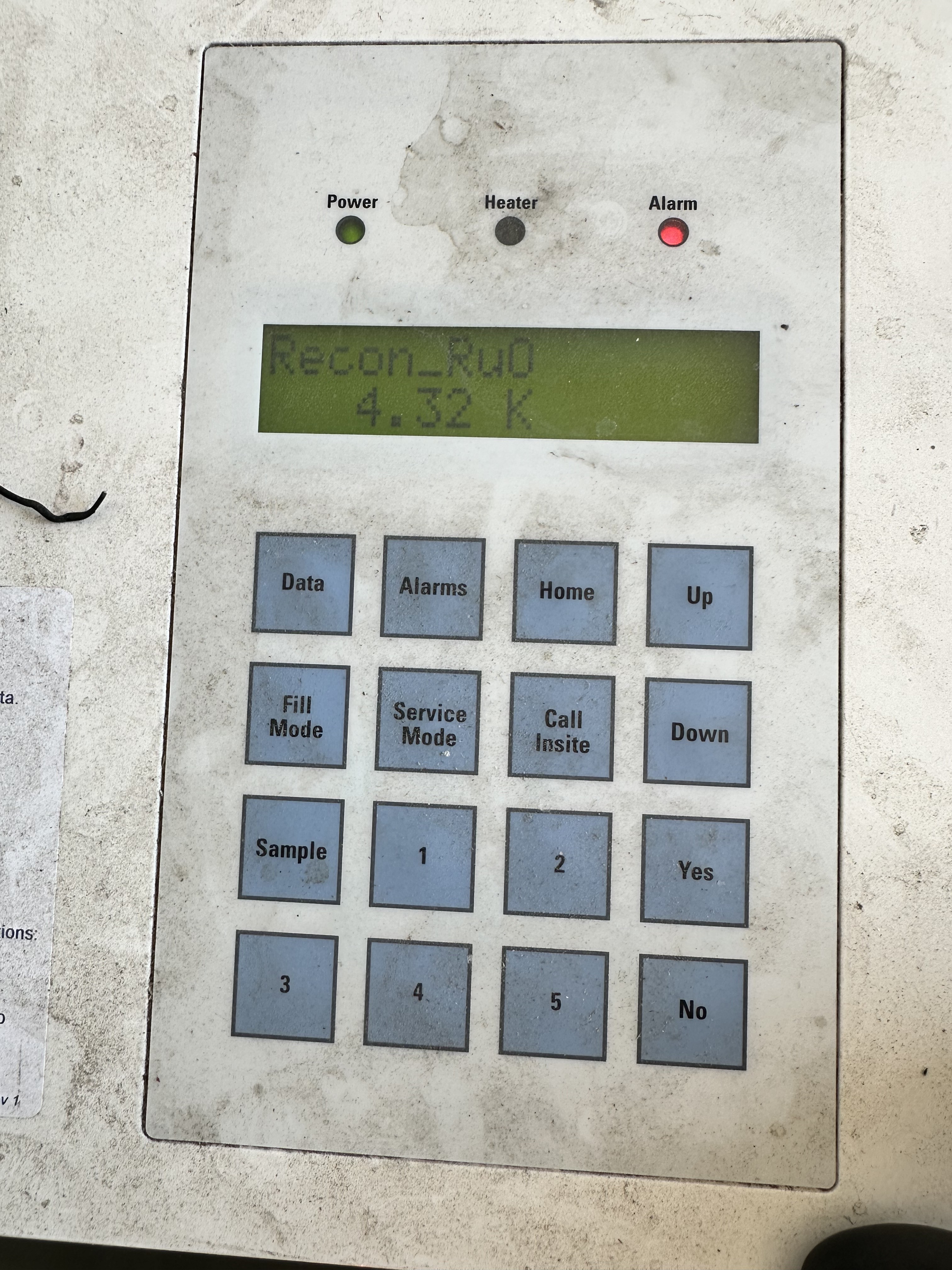
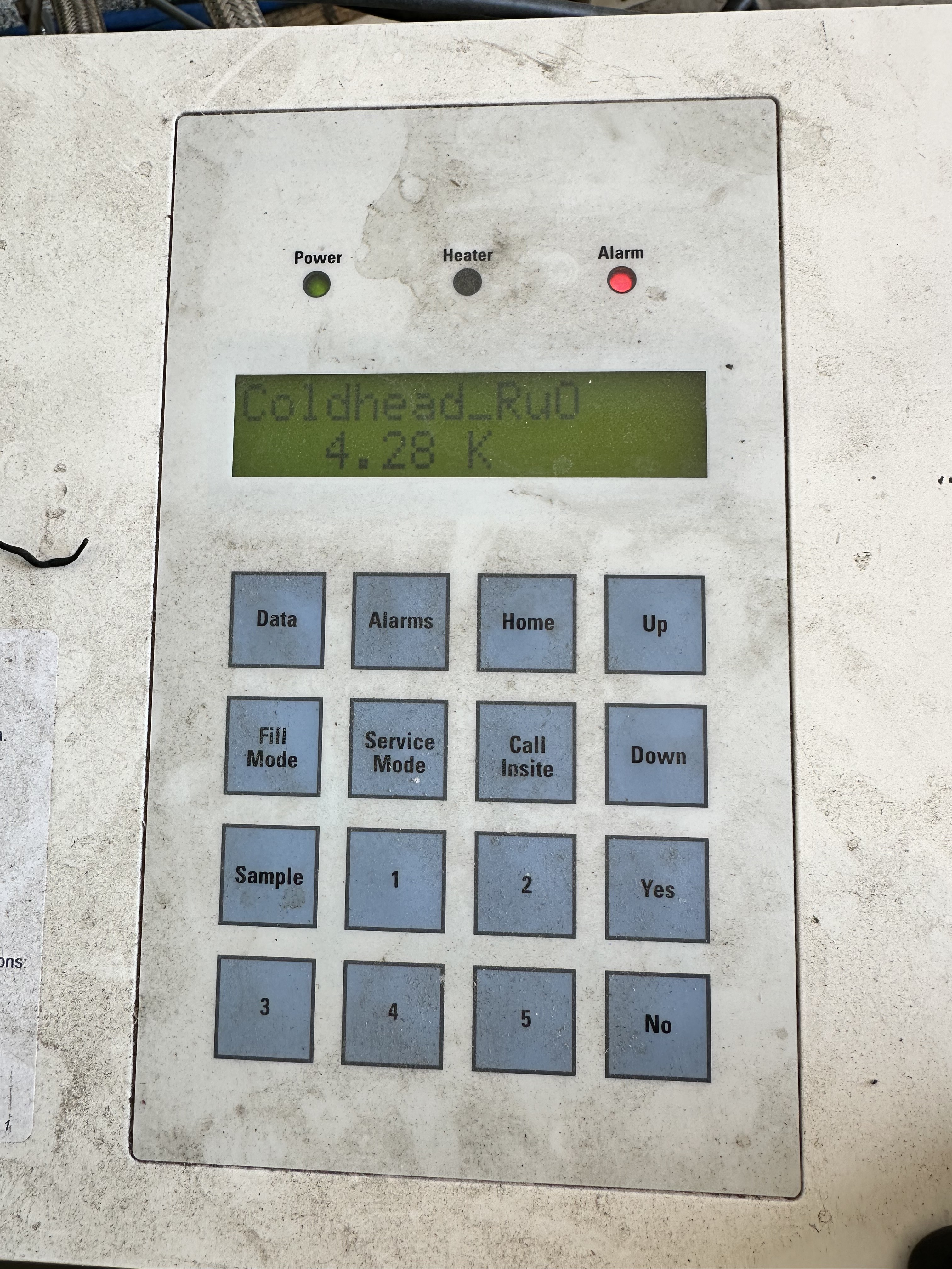
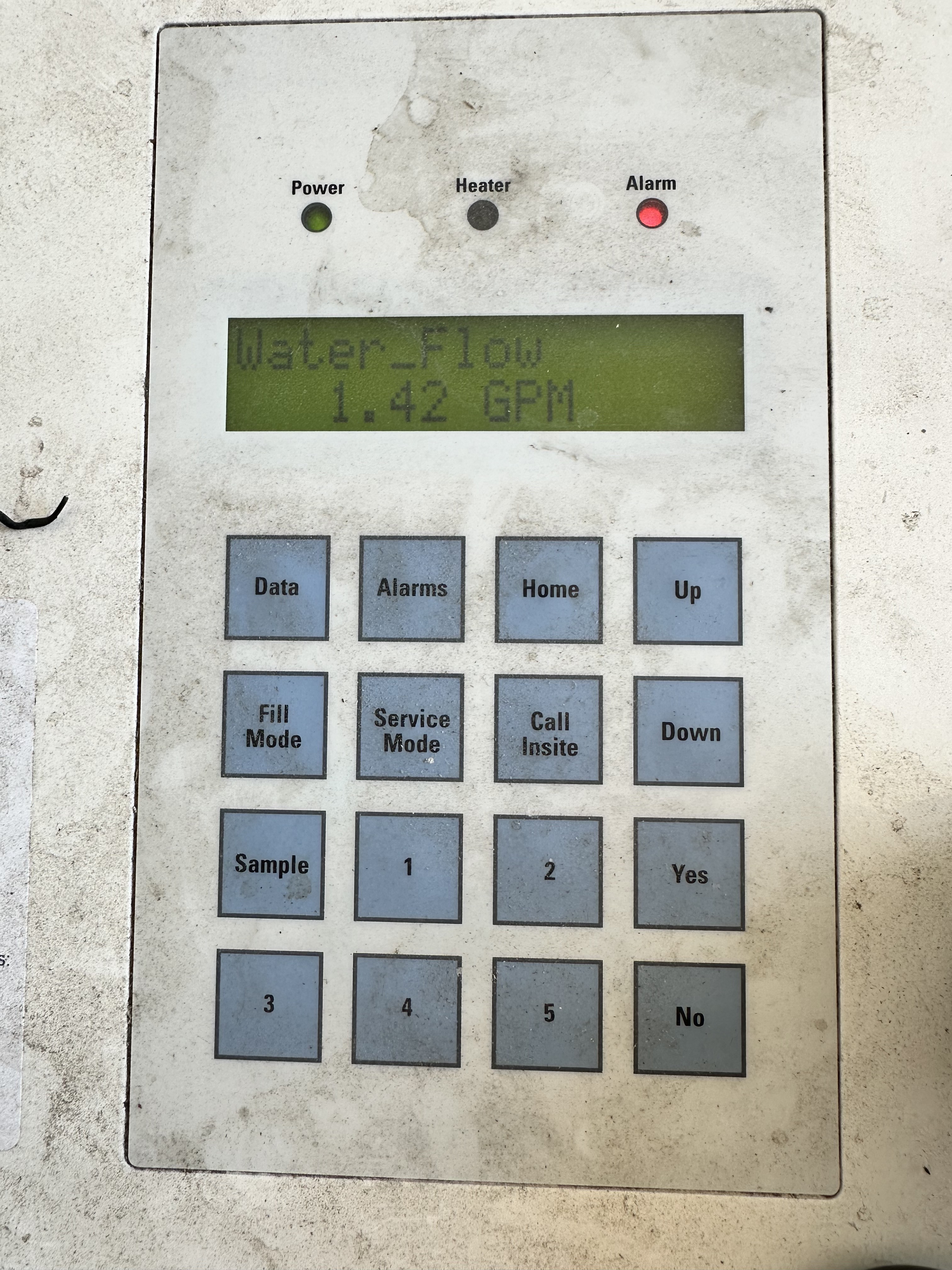
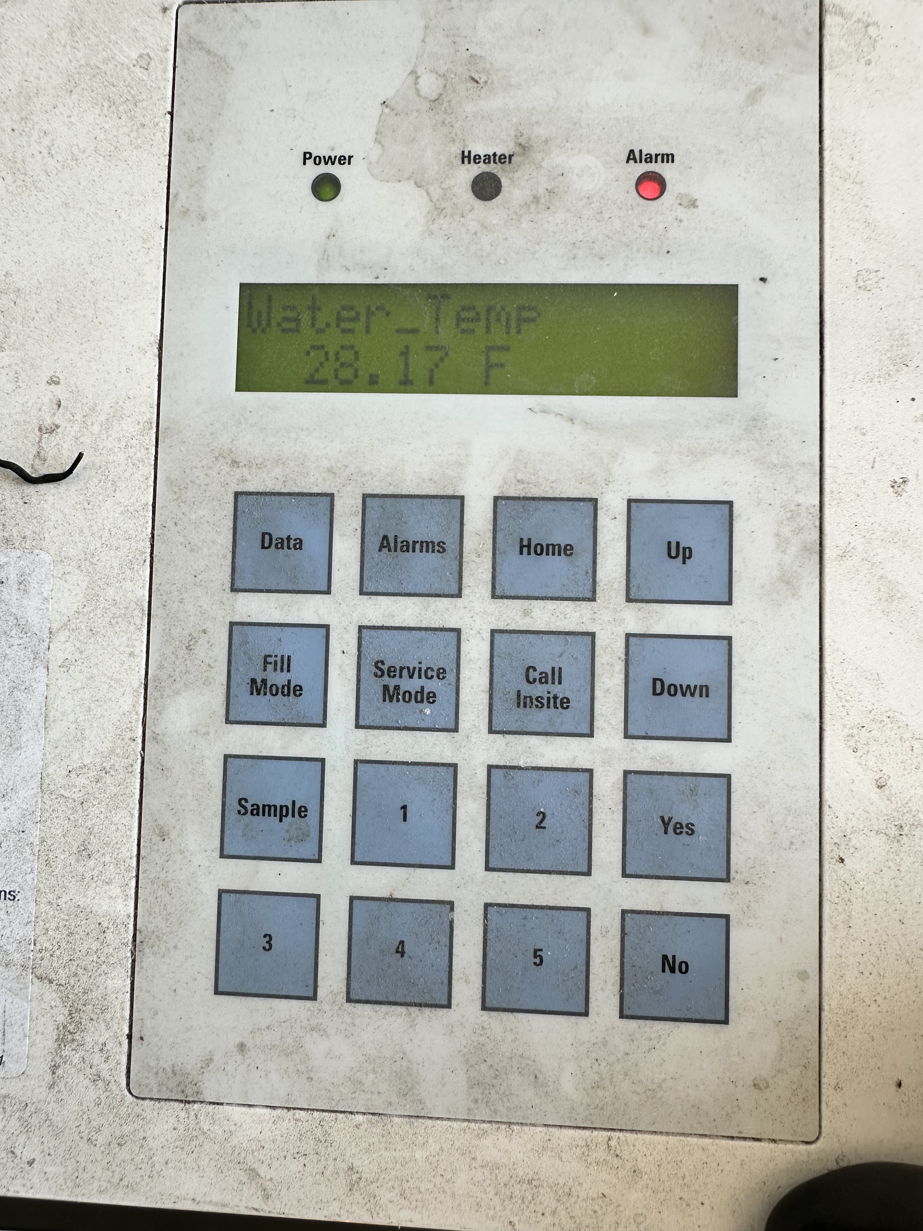
Once all the cables are secure, power on the MM3 and verify that all the data is populating.

Recording Magnet Info
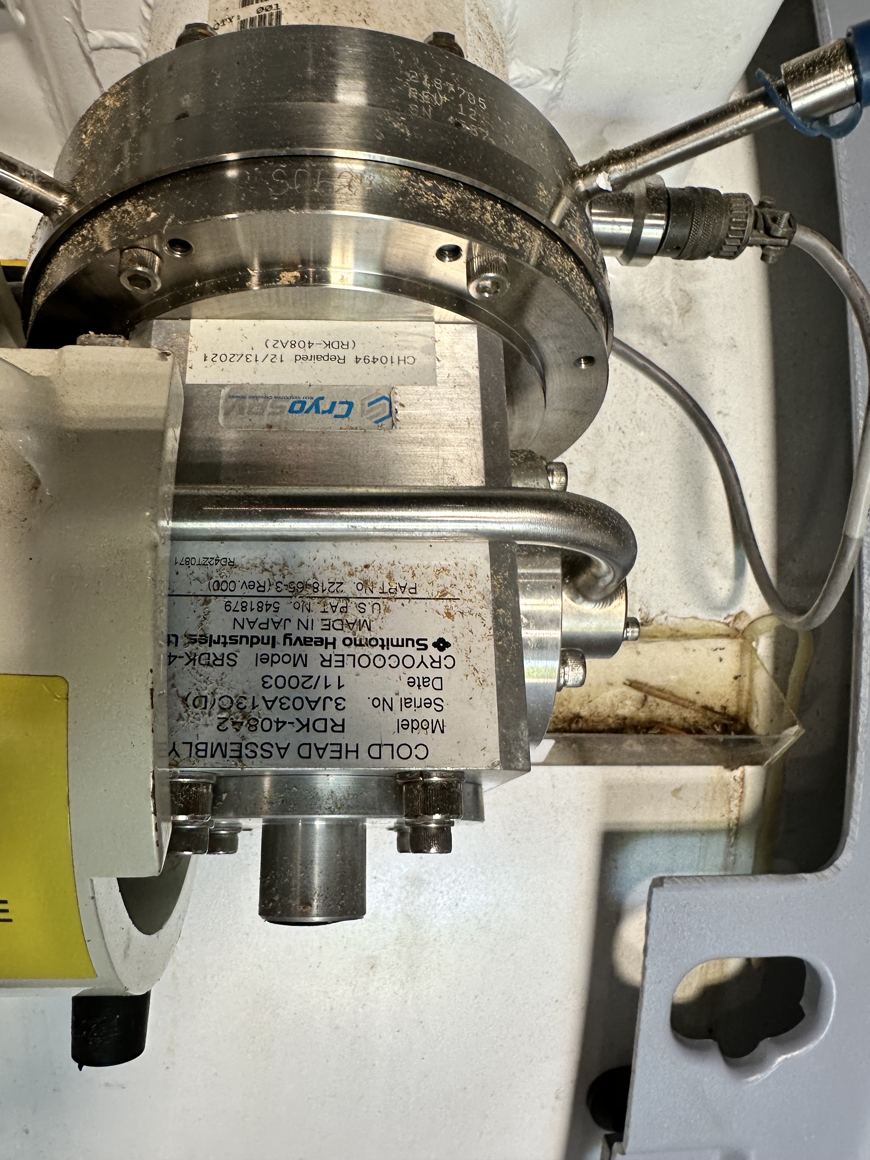
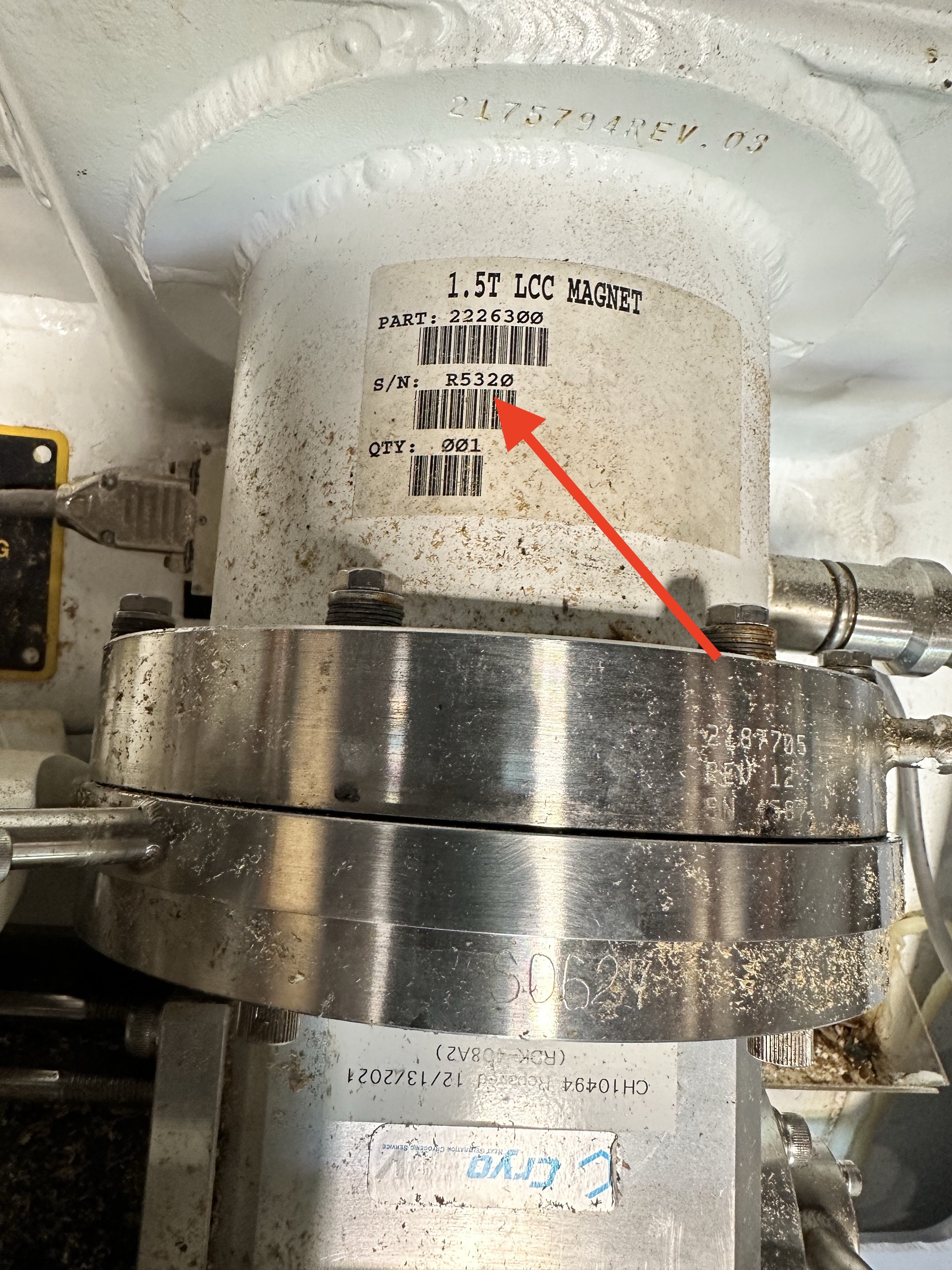
The cold head and the magnet serial number need to be recorded upon delivery and reported to the CryoSRV sales department.
Final-step
Once the magnet is added to the asset data the magnet data must be logged with the storage magnet readings form in Airtable.